
|

|
Forum Index : Electronics : Building a new Inverter.
| Page 1 of 8 |
|||||
| Author | Message | ||||
| Gizmo Admin Group Joined: 05/06/2004 Location: AustraliaPosts: 5078 |
Hiya I live off grid with a combination of solar and wind power. My inverter is a Latronics LS7000, 7kw model, and has been brilliant. Apart from a couple of restarts in the last 3 years, its been reliable. From what I hear from the neighbours, the local grid power drops out every few weeks and is pretty unreliable, so I can say off grid power is much more reliable than grid power ( despite what the Energex CEO would like you to think ). I like to have backup systems, and we get a lot of lightning storms around here, so for some time I've wanted a backup inverter, in case the Latronics gets fried by lightning. But 48v inverters are expensive. I need a inverter that will use my existing 48v battery bank, and supply 3 or so kw, basically run my house, until I can get the other inverter fixed. You can buy cheap inverters for under $1000, but these have poor build quality control, rarely reach their rated power, and basically need a couple hours work modifying them to make then reliable. Recently Oztules ( John ) started a thread over at the Fieldlines forum, detailing how he built his own high power inverters using parts from retired grid tie inverters and ebay parts. Link. For around $500, and good bit of hard work, he's built inverters capable of over 6kw continuous use. And the advantage of building your own is you have control over the build quality, and a better chance of fixing it if it goes bang! Oztules uses the toroidal transformer from a Inspire 1.5kw grid tie inverter. This is a 130v / 240v transformer, with a single 2mm diameter copper winding on the outside, the 240v, and a 2 in hand 2mm winding on the inside, the 130v. Oztules uses two of these toroidal transformers to build a monster transformer. He removes both windings, glues the cores together, and winds a new secondary 240v winding and a low voltage primary winding. Locally I could not find a Inspire 1.5kw, but I did find a Inspire 2.5kw model in Brisbane for $125. I had to pick up some 2nd hand solar panels from the Gold Coast anyway, so made a day trip, 700km, $70 fuel and I'm the owner of a Inspire 2.5kw, plus 8 190 watt panels ( another story ). Next day I pulled the Inspire apart. Pretty impressed with the build quality of these. The toroidal is massive, weighs about 25kg and is 220mm in diameter. The circuit board has lots of goodies too. 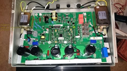
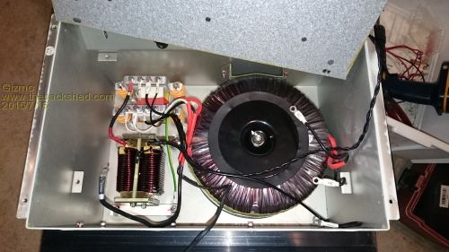
Next I needed to remove the core, and this was different to the 1.5kw model transformer. My core was filled with some sort of epoxy, so I had to gently chip away at it for an hour until I could carefully tap out the core. 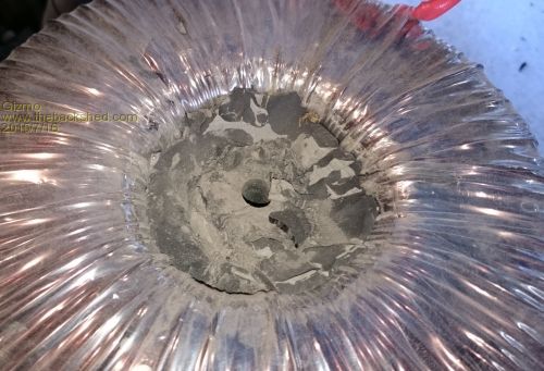
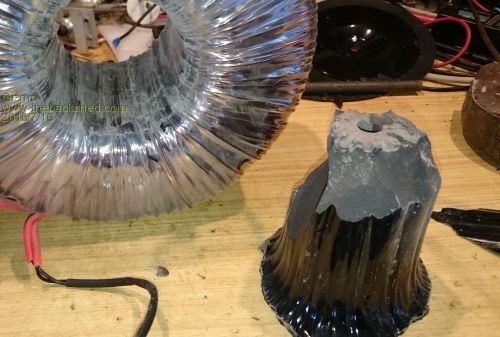
Then I removed the outer tape layer to expose the outside winding, and set it up to do some tests as Oztules suggested. 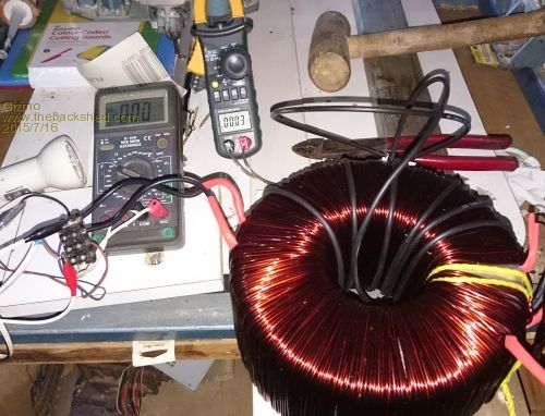
After a few tests and "ah-ha" moments, I discovered, that, unlike the 1.5kw model Oztules used, the 2.5kw model transformer has the 240 winding on the inside. And since its a higher capacity inverter, the 240v winding is 2 in hand 2mm copper. Boy will that save me a lot of work! So all I need to do is remove the outside winding, and wind a new primary. 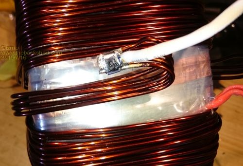
The primary was 4 in hand 2mm copper, so was going to be a bugger to unwind without damaging the copper. I couldnt use the method Oztules used, so I ended up propping the transformer up in the middle of the yard and unraveled the 4 wires by grabbing the next loop, and taking it for a walk until the end of the wires passed through the core. Towards the end the wires were getting over 30 meters, so I did a lot of walking that day. Once done, I rolled the wire onto a spare spool for a later project. 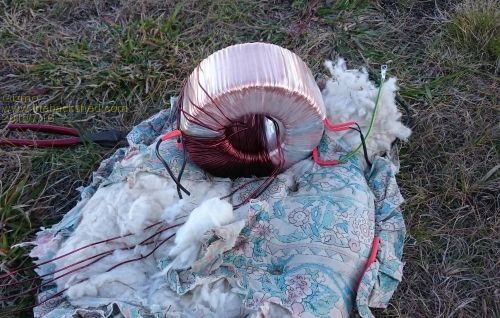
Below is a picture of the 240 winding showing its 2 in hand. This was buried under many layers of tape, but I needed to see how it was wound so did a little explorative surgery. 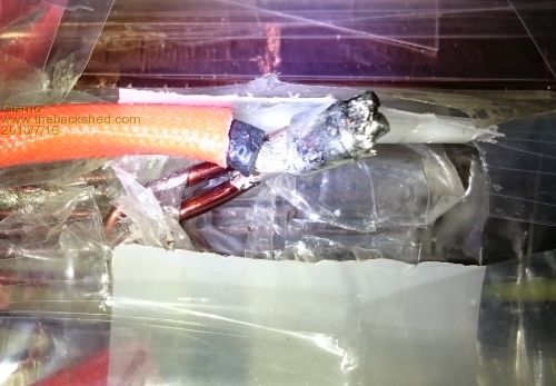
And the core ready for a new primary. The hole in the middel is now 90mm diameter. 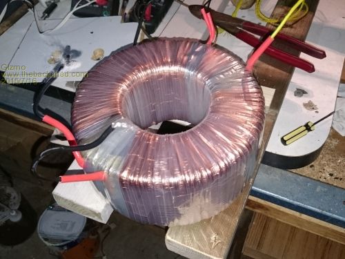
Next post I'll show the new primary in place. The primary wire is 25mm square, 9mm diameter with insulation. Glenn The best time to plant a tree was twenty years ago, the second best time is right now. JAQ |
||||
| yahoo2 Guru Joined: 05/04/2011 Location: AustraliaPosts: 1166 |
there is a topic on energy matters forum that adds a bit more detail listed under the topic W7 powerstar inverter modification (122 pages) I very nearly drove to Melbourne and picked up a uteload of inverters to play with, they look very handy. I am interested to see your version, Glenn. I'm confused, no wait... maybe I'm not... |
||||
| Gizmo Admin Group Joined: 05/06/2004 Location: AustraliaPosts: 5078 |
Different project Yahoo, but same idea. Thanks for that link too. This one is using the toroidal as above, and replacement boards for the cheap Power Jack inverters. So basically, I've ordered a MOSFET and controller board to suit a 8kW pure sinewave Power Jack inverter, and will fit those in the Inspire case, along with the rewound transformer. Glenn The best time to plant a tree was twenty years ago, the second best time is right now. JAQ |
||||
| brucedownunder2 Guru Joined: 14/09/2005 Location: AustraliaPosts: 1548 |
All looking good Glenn. This is exactly how I modified my W7 . The core was difficult to remove,but just wait til you come to installing the 25mm wire or the primary,!!!!. Mine is working perfect,drawing very little standby current,around 20 watts. It runs very cool, has a small ,hum, when pushed above 1200 watts. My photos are listed somewhere here, and on the field lines forum. Hard work on my 71 yo fingers, but I got there. Bruce Bushboy |
||||
| BobD Guru Joined: 07/12/2011 Location: AustraliaPosts: 935 |
This 25mm wire, is that the cross section area in MM^2? |
||||
| Gizmo Admin Group Joined: 05/06/2004 Location: AustraliaPosts: 5078 |
Yeah Bob, 25mm^2. Not looking forward to it Bruce, the wire is very stiff. Its also too cold at the moment, my fingers are pretty useless. Warms up next week so I'll tackle it then. The circuit boards are still a few weeks away, so no rush, plus I have to mount those 8 solar panels and rebuild my charge controller to handle the extra current, so got heaps to do in the mean time. Glenn The best time to plant a tree was twenty years ago, the second best time is right now. JAQ |
||||
| yahoo2 Guru Joined: 05/04/2011 Location: AustraliaPosts: 1166 |
the energymatters topic gets to the powerjack replacement boards eventually and a few issues like driving fans and sorting the control wiring if you have no working inverter to copy. I would list the post numbers but my memory is a bit hazy and I dont want to go through the pain of reading it all again. I'm confused, no wait... maybe I'm not... |
||||
| Gizmo Admin Group Joined: 05/06/2004 Location: AustraliaPosts: 5078 |
Hi Yahoo Yeah been reading through it, your right. Bit of light reading to do 
Glenn The best time to plant a tree was twenty years ago, the second best time is right now. JAQ |
||||
| brucedownunder2 Guru Joined: 14/09/2005 Location: AustraliaPosts: 1548 |
Hi Glenn, and the other lads. Yep , there's a lot of reading on that mod subject . Contact Oztules(john) if you get stuck , . He's done most of the groundwork concerning the "buy,ing of the boards" Etc. They are fairly cheap and thats the way I'll go if I have to . Mine is on 24/7 and is working perfect .. You,ll have a lot of satisfaction , once you get the lot together. John installed a couple of e-bay purchased volt and amp meters in his housing --the same as yours. Bloody cold and windy here, seeing 0.c. degrees on the outside temp. often... have fun ,,,Bruce Bushboy |
||||
| VK4AYQ Guru Joined: 02/12/2009 Location: AustraliaPosts: 2539 |
Hi Glenn Do you have the link for the PJ powerboard I have some of these inverters and would like to have a go at converting one. All the best Bob Foolin Around |
||||
Grogster Admin Group Joined: 31/12/2012 Location: New ZealandPosts: 9308 |
Is there any reason why nobody uses a welder transformer as the basis of an inverter like this? Welder tranny's have a 230v primary usually 10-15 amps or so continuous rating, and secondary of about 30-60v at anything up to a couple of hundred amps. In reverse, drive the welder electrode side, with the generated mains voltage now appearing on what was the 230v primary of the welder transformer. No re-winding needed. I am guessing I am missing something obvious here - probably efficiency. Welder transformers are probably no where near as efficient as this toroidal arrangement..... Smoke makes things work. When the smoke gets out, it stops! |
||||
| Tinker Guru Joined: 07/11/2007 Location: AustraliaPosts: 1904 |
Yes that, but welding transformers are also deliberately designed to be very lossy. One requires a higher voltage to start the welding arc but that voltage drops to a much lower one once the Amps start to flow. Some regulate the output by moving part of the core to change efficiency, others use a tapped secondary winding. I have never seen a toroid core in a welder. Toroid cores are much more efficient and also quieter, in an inverter as low as possible standby (no load) current is what one aims for. Klaus |
||||
Grogster Admin Group Joined: 31/12/2012 Location: New ZealandPosts: 9308 |
Ahhhhh - OK, thanks for that. I knew there must be a reason, or people would have been doing it that way, but I could not think what that reason was. Thanks.  Smoke makes things work. When the smoke gets out, it stops! |
||||
| Gizmo Admin Group Joined: 05/06/2004 Location: AustraliaPosts: 5078 |
Hey Bob. Link to ebay Bit of a backlog, I think they build them as orders come in. I placed my order over 2 weeks ago and they haven't been despatched yet. I ordered the 8Kw board and matching controller. The 8kW would be good for 4kW realistically. Prices have gone up since Oztules article, I ended up paying about $365 for both boards plus the ( overpriced ) shipping. So all up, the inverter will cost me about $550 plus time and labor. Yeah Grogster, Tinker is spot on. The big feature of a toroidal based inverter is low idle current. A E cored based inverter can draw many amps even though there is no load, a toroidal inverter can draw less than half an amp. The problem with toriodals is price, they are much harder to make. Glenn The best time to plant a tree was twenty years ago, the second best time is right now. JAQ |
||||
Grogster Admin Group Joined: 31/12/2012 Location: New ZealandPosts: 9308 |
So, you buy the controller and the mainboard for a matching inverter output, then couple that to your battery bank and custom wound toroidal transformer, yes? Very interested in this idea, and certainly seems like a much safer way to spend your hard earned cash, then on one of those 10kW inverters from China that can only do about 1500W continuous..... As we all know with physics etc, there is no such thing as a free lunch, so having an inverter that can give you, say, 6kW continuous via this method, must therefore be sucking some SERIOUS amps from the battery bank side of things. Just how long can an inverter like that supply that kind of load? Assume decent quality deep-cycle batteries, heavy battery wiring - all that is required for a correct setup not an el-cheapo one with cruddy batteries and cruddy wiring to save cash...... Smoke makes things work. When the smoke gets out, it stops! |
||||
| VK4AYQ Guru Joined: 02/12/2009 Location: AustraliaPosts: 2539 |
Thanks Glenn I have ordered a set 8kw 24 volt boards lets see how long they take to come. All the best Bob Foolin Around |
||||
| yahoo2 Guru Joined: 05/04/2011 Location: AustraliaPosts: 1166 |
I dont think there is an answer to that question. If you disregard failure due to faulty components which is usually covered as a warranty issue in the first few months with a purchased inverter, then the place to look would be the parallel transistors that handle the switching. you could probably answer this better than us, my guess is that they fail from to small amounts of cumulative damage that occur when the inverter is pushed to extreme loads for short periods and the heat dissipation cant keep the junctions from melting. I cant think of any practical scenarios where I would be able to load a large off-grid inverter with a consistent 75% load continuously. It would have to be on a dedicated circuit and be driving something like a bank of water pumps for aquaponics or grow lights for ...ahem... pharmaceuticals or vegies or perhaps heat lamps for piglets or poultry in a hatchery. It is not uncommon to see an inverter sit at 40% load for long periods of time with the occasional load at 150% for a few minutes most inverters seem to handle that quite happily for a very long time. I'm confused, no wait... maybe I'm not... |
||||
| Gizmo Admin Group Joined: 05/06/2004 Location: AustraliaPosts: 5078 |
Some updates. The Power Jack boards arrived after a few weeks. Looks like they build the boards as orders come in, but once despatched it arrived in a couple of days. No idea how to connect it up, so I've been reading through the W7 inverter thread over at Energy Matters forum for clues, but I think I will play it safe and wait for Oztules to post part two of his build on the Fieldlines forum. 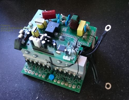
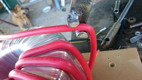
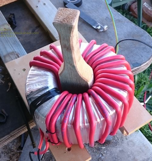
Started on the transformer. Winding the 25mm wire is tough work, but I made a bending tool and a timber wedge tool to help bend the wire for a neater finish and shorter wire length. 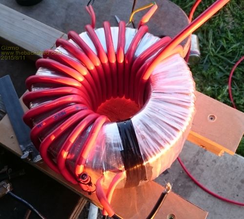
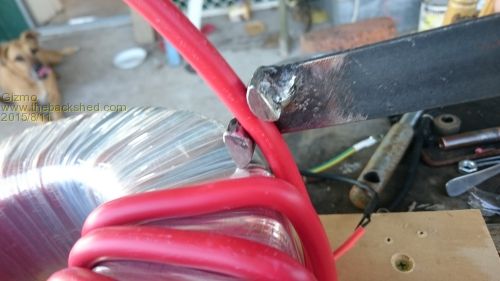
Next I'll do some tests and post how it goes. Glenn The best time to plant a tree was twenty years ago, the second best time is right now. JAQ |
||||
| VK4AYQ Guru Joined: 02/12/2009 Location: AustraliaPosts: 2539 |
Hi Glenn My boards turned up to day but I have been to busy to get started, I have a Inverter that these boards go in so a slight dismantle and some pictures may help in that department, nice job on the transformer, could I use welder lead flex to do the job as it is a lit easier to bend or would the losses be to great with all the separate strands? All the best Bob Foolin Around |
||||
| Gizmo Admin Group Joined: 05/06/2004 Location: AustraliaPosts: 5078 |
Hi Bob Yeah some photo's would be handy. There is a long row of pins that I guess are for indicator LED's, plus a couple of other connectors. But I would hate to take a guess and damage the board, cant afford another one. Yes to the welding wire. I read you can use welding wire a few hours after I bought the PVC coated electrical wire  . So long as the welding wire has the square mm rating, it doesn't matter if its made of finer strands of wire. The welding wire usually has two layers of insulation, you can take off the outer, reduces the diameter and makes it even easier to wind. . So long as the welding wire has the square mm rating, it doesn't matter if its made of finer strands of wire. The welding wire usually has two layers of insulation, you can take off the outer, reduces the diameter and makes it even easier to wind.
I ended up with 25 turns on the first layer, then added a further 7 turns, which made it a bit messy. I connected up the transformer secondary in series with a 60watt bulb and powered it up. The secondary was sitting at 220vac, and the primary had 35v. If I do the math for 230vac, the primary would be 36.5vac. After reading the forum threads on Fieldlines and Energy Matters, I think I should take off 3 turns to get that voltage closer to 33vac. There is a lot of info in the Energy Matter thread about this, but at over 120 pages, it takes many hours to find the useful bits and I'm still only a third of the way through it 
I also ordered the ferite cores discussed in those forums, should be here in a week or two. The cores are a big factor in reducing the idle current. Glenn The best time to plant a tree was twenty years ago, the second best time is right now. JAQ |
||||
| Page 1 of 8 |
|||||