
|

|
Forum Index : Electronics : help with circuit
| Page 1 of 2 |
|||||
| Author | Message | ||||
| irishron40 Senior Member Joined: 22/09/2014 Location: IrelandPosts: 251 |
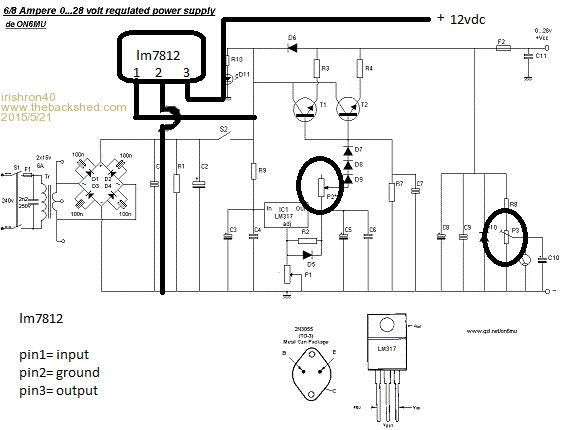
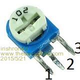
hi . can someone please explane to me which way I connect the trimpot p3 am i correct in thinking at( leg 1 goes to negative) ( leg 2 goes to c10) (leg 3 goes to r8) also what is p2? that isnt a trimpot is it? and do i only use the middle and 1 outer pin on p1? thanks for being patient with a beginner ron |
||||
| powerednut Senior Member Joined: 09/12/2009 Location: AustraliaPosts: 221 |
Hi Ron, Interesting circuit. I don't think I've ever seen the bridge rectifier done quite that way. Anyway, for the trimpot on the far right of the circuit you connect either leg 1 or leg 3 to ground, and then the other pin to R8. The middle pin (leg 2) connects to C10. That allows you to connect the trimpot either way round for ease of access. P2 looks like its probably a potentiometer (aka pot, or variable resistor). In that circuit I think its controlling the output voltage. Is the 7812 portion added by you? If your just planning on using it as an extra line for running some small stuff then it might work okay, but you should probably add some output filtering. You won't get 6-8 amps out of it though if that is what you are expecting. I've been seeing a few power supply posts from you - what are you actually trying to do? |
||||
| irishron40 Senior Member Joined: 22/09/2014 Location: IrelandPosts: 251 |
im just a beginner ,but getting hooked lol. the 7812 i put in to run my 12volt cooling fan and supply to my usb charger which requires a 12v input. thats all i use the 7812 for it says the following on the page of power supply diagram P2 47 Ohm or 220 Ohm 1 watt * (be sure you can reach 0 ohms as any resistance limits the current) I like to know what it is and how to connect it. thx for confirming trimpot P3 http://electronics-diy.com/power-supply-lm317-2n3055-0-28v-6-8a.php ron |
||||
| BobD Guru Joined: 07/12/2011 Location: AustraliaPosts: 935 |
Ron Unless you wish to have adjustable current limiting in your supply you can use a piece of wire instead of P2. If you do use it then it has to take a substantial current which will produce heating. Hence the 1 W (as in Watt or power) rating. If I was building the supply I would connect directly from the OUT leg of the LM317 to the bottom of diode D9. Save money. 
I would put a 100nF 16 volt (or 25 volt) capacitor on the output of the 7812 else it may become unstable. It wouldn't hurt to do the same for the input. Put them close to the 7812! Do us all a favour and use the link button on the editor toolbar to make a link instead of just pasting it straight in. The Link button is fourth from the left next to the underline button. It makes the link live and clickable in your post. You can also abbreviate and name the link. Examples: http://electronics-diy.com/power-supply-lm317-2n3055-0-28v-6-8a.php or circuit diagram and don't forget to do a Preview of your post and test the links. all the best Bob Note that I did a correction from P3 to P2 at the top. |
||||
| irishron40 Senior Member Joined: 22/09/2014 Location: IrelandPosts: 251 |
thank you. I indeed like to have current limiting . I am after building this casing. it has main power switch and fuse on the left 2 openings ( 1 for amp meter for current limiting , and 1 opening volt my combined volt ampmeter , as I also like to see what current my load will be drawing) on right it has a 5vdc output which will accept 12v in. also a fuse and switch to switch of output temporarily it has speaker connectors and just have to fit my original bench suppky output fittings. this is my first project and i do have a lot to learn, but Ill get there. it says p2 is a varistat. ( what is a varistat?) and how do i connect that? you said (Note that I did a correction from P3 to P2 at the top. ) what did you mean? 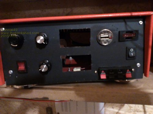
|
||||
| BobD Guru Joined: 07/12/2011 Location: AustraliaPosts: 935 |
In the email I got confused between P2 and P3. The email said piece of wire instead of P3 and should have said piece of wire instead of P2 A varistat is a variable resistor. Like a trimpot only larger. Variable resistors can be called varistat, rheostat, potentiometer, trimpot, trimmer, and I have probably missed one or more out. The differences are usage and physical construction. Read the link on resistors and then in the Potentiometers section follow the link to Potentiometers. http://en.wikipedia.org/wiki/Resistor |
||||
| irishron40 Senior Member Joined: 22/09/2014 Location: IrelandPosts: 251 |
thx Bob i had a read thru that. ( interesting) so looking at that diagram Is my understanding right that that is the potentiometer on front panel for current limiting? and is it only connected by the middle and one side pin? I read also somewhere that you should shorten the 3 pin with the middle pin. is this correct? thank you. ron |
||||
| BobD Guru Joined: 07/12/2011 Location: AustraliaPosts: 935 |
|
||||
| irishron40 Senior Member Joined: 22/09/2014 Location: IrelandPosts: 251 |
thank you Bob. just wonder one thing which may be simple to you all. I thought the higher the resistance of a resistor the more volt and current it will refuse to flow. p2 is a 47 ohm . how can a 47 ohm resistor limit that much current? I thought It should have been rated far higher. Like I said. It just sound like logic to me a beginner lol ron |
||||
| Gizmo Admin Group Joined: 05/06/2004 Location: AustraliaPosts: 5078 |
Have a play around with ohms law, it explains the relationship between ohms, volts and amps. See http://www.thebackshed.com/windmill/Docs/ElectricFormular.asp Glenn The best time to plant a tree was twenty years ago, the second best time is right now. JAQ |
||||
| irishron40 Senior Member Joined: 22/09/2014 Location: IrelandPosts: 251 |
just have 3 questions to finish my project. 1 in attached file I have a red circle around a neg connection. why is this illustrated? isnt it a negative connection anyway ? 2 P1 shows middle and outer leg connected. what do I do with other outer leg of potentiometer 3 C8 is a 330uF/50v I dont have 330. how important is this vallue in this location? thanks. ron 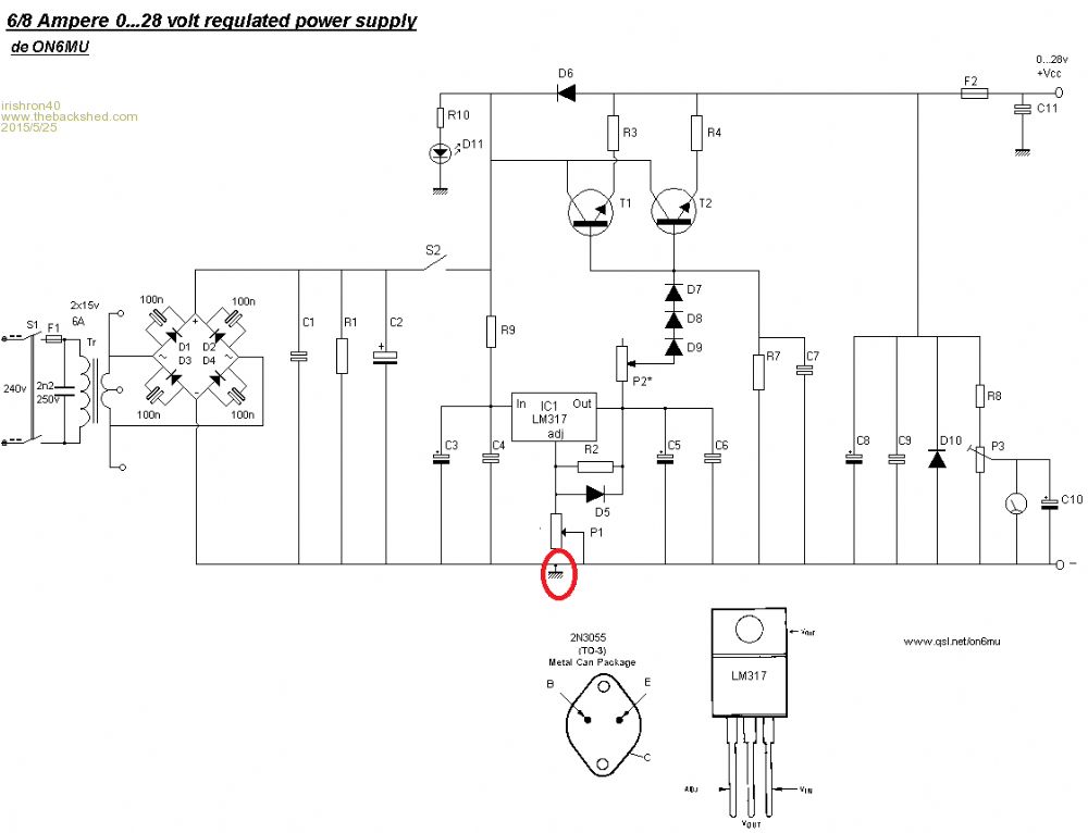
|
||||
| Gizmo Admin Group Joined: 05/06/2004 Location: AustraliaPosts: 5078 |
1. Its connected to the chassis. Not necessary, but note C11 and D11 are also connected to chassis, so these will need to be connected to the -ve rail. 2. Nothing. 3. Its the output filter cap, so you can use anything between say 220 and 470 without any affect. Glenn The best time to plant a tree was twenty years ago, the second best time is right now. JAQ |
||||
| irishron40 Senior Member Joined: 22/09/2014 Location: IrelandPosts: 251 |
i had c11 and d11 alleady to the neg rail thx glenn. its a lot to learn, but im only messing about for a few weeks, so slowly getting there. thx ron |
||||
| irishron40 Senior Member Joined: 22/09/2014 Location: IrelandPosts: 251 |
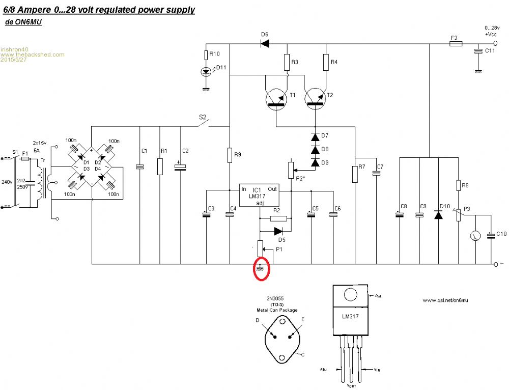
I connected it up and had a slight buzzing sound as if there is a short circuit. but no voltage on output I did disconnect the tip3055and buzzing was gone. checked voltage with multimeter . I have voltage coming in and out of lm317 and can regulate voltage also. I also have voltage at D7 so I hav no positve on output and also no postive on the connection for voltmeter I tried different tip3055 but still no output. left pin 3055 I connected to base ( comming from D7) Middle pin to power in from switch S2 and right pin to 10watt resistor with then is connected to positive output line. what am I doing wrong?? thx ron thx |
||||
| Gizmo Admin Group Joined: 05/06/2004 Location: AustraliaPosts: 5078 |
Dont know. Time to fault find. With the power transistors removed, connect the output of D7 to the output fuse, and see if the volt meter then reads anything? I suspect there is a short somewhere in the output circuitry. The best time to plant a tree was twenty years ago, the second best time is right now. JAQ |
||||
| irishron40 Senior Member Joined: 22/09/2014 Location: IrelandPosts: 251 |
i did try that glenn, but no output either then. i look again tomorrow its 5am noe here in ireland, dont know wher you all are based. but here its bed time. thx and good night. |
||||
| Gizmo Admin Group Joined: 05/06/2004 Location: AustraliaPosts: 5078 |
Sounds like a short on the output somewhere. Check D10 is facing the correct way. Start removing parts of the circuit until it works, suspect anything after the transistors, look for shorted PCB tracks. Most of us are in Australia, about 10 hours ahead of your time. Glenn The best time to plant a tree was twenty years ago, the second best time is right now. JAQ |
||||
| irishron40 Senior Member Joined: 22/09/2014 Location: IrelandPosts: 251 |
voltage into lm317 is 17.49v output of lm317 is 16.18v because of voltage drop from D7,D8,D9 i have at fuse F2 14.2 volt at D10 i read 14.2 but at between R8 and P3 ,I only read 6 volts. I double checked and i did use a 10 K at R8 Im lost. could the resistor R8 be faulty? cheers ron |
||||
| BobD Guru Joined: 07/12/2011 Location: AustraliaPosts: 935 |
Ron The voltage at R8 P3 is OK. R8 and P3 are both 10K ohms each so the voltage between should be approximately half of D10 reading. Since part P3 resistance is modified lower by the parallel resistance of the meter then that should cause the voltage at R8-P3 to be a little lower than half of 14.2. 6 volts is probably exactly correct. Just a check on the fuse, what is the voltage at C11? It should read about 14.2 volts also. If that is OK then the circuit as it stands is working OK. All you have to do is then put those big transistors back in circuit. Bob |
||||
| irishron40 Senior Member Joined: 22/09/2014 Location: IrelandPosts: 251 |
i am a little confused i do have the 14.2 at the fuse I see between p3 and c10 a volt meter displayed.. I thought that is where i connect my volt meter. so what is the story there bob? thanks ron |
||||
| Page 1 of 2 |
|||||