|

|
Forum Index : Electronics : power supply
| Page 1 of 2 |
|||||
| Author | Message | ||||
| irishron40 Senior Member Joined: 22/09/2014 Location: IrelandPosts: 251 |
hi I am buil;ding a power supply from this diagram http://electronics-diy.com/power-supply-lm317-2n3055-0-28v-6-8a.php can I change the lm317 for a lm338 and what would be the approx amps in conjuction with two tip3055 transistors? and C10 is a 1uF/16v. would it be ok to use a 1uF/50v? i have 2 TIP3055 transistors, I believe they are the same as the 2n3055. thank ron |
||||
| Pete Locke Senior Member Joined: 26/06/2013 Location: New ZealandPosts: 181 |
Pretty much, yes. The 338 is a 5amp reg, the 317 is only 1.5amp. Seems a wast of the extra power available from the 338 but would be fine. The TIP3055 is the same spec wise as the 2N3055, just a different case. No problem using a 50v cap in place of a 16v one. Good luck with the project. Cheers Pete'. |
||||
| irishron40 Senior Member Joined: 22/09/2014 Location: IrelandPosts: 251 |
thx pete. would that 338 combined with 2 tip3055 give me about 15 amp? thx ron |
||||
| Pete Locke Senior Member Joined: 26/06/2013 Location: New ZealandPosts: 181 |
Easily. As long as the supply (transformer and rectifiers) are up to the task. The 338 is wrapped up in cotton wool with all the power being handled by the 3055's. 15amps being shared by two transistors each capable of taking the load on their own is always a good thing. Only make sure the heat sink is up to the task. Bigger is better :-). Should go well. Good luck. Cheers Pete'. |
||||
| irishron40 Senior Member Joined: 22/09/2014 Location: IrelandPosts: 251 |
thx pete. appreciate your comment. I am just starting of with electronics, but love it. Transformer is from microwave that i wired with 27 amp cable. the heatsink is about 7 x 10 cm and has the two 3055`s and the rectifier. lm338 is on a separate small heatsink. I also have a little fan which i will connect up to allow enough cooling. just wonder as i dont have all those types of diodes would it be ok to use all n4007 diodes? thx again. ron |
||||
| Pete Locke Senior Member Joined: 26/06/2013 Location: New ZealandPosts: 181 |
No and NO!...... A microwave transformer has a primary winding designed for ...at best... a 50% duty cycle. That simply means that given a turn on period of 30 seconds on, then 30 seconds off. If you run them at 100% duty (always on) then somewhere down the track the smoke will come out. Microwave oven transformers are a great platform to make spot welders out of. Short duty requirements of lots of horse power. Not a good transformer to use for your project, even though it might be good for re winding practice. The 1N4007 diodes are only good for 1amp. If you want horse power for your power supply, start with a transformer designed for 100% duty cycle. Back in the day I used to get transformers form old valve black and white Tv's. Hard to find now :-) Do a Google search for 50amp bridge rectifiers. It will take you to something that will give you a suitable component. That covers the front end of the power supply. The back end (regulator) looks good, although old school. You have an analogue regulator that spills wasted energy as heat. I'm not sure what you are looking for in a power supply or what you want to do with it. Analogue regulators are a great place to start in the learning curve (The curve can be VERY steep :-) with this field. Later you will discover 'BUCK' regulation and eventually switch mode or self oscillating supply's. But go for gold with what you have on hand. If time is not a problem, then re wind that microwave transformer and prove me wrong with the smoke part. Get stuck in and LEARN while you're in the shed in the weekend. Let the smoke out of a few things discovering the wonderful world of Voodoo electrickery. We've all been there in varying degrees. It's the best way to learn  |
||||
Downwind Guru Joined: 09/09/2009 Location: AustraliaPosts: 2333 |
I have rewired many and used them as battery charges running for long periods and they still retain the smoke within them after years of use, most of mine run at around 20 amp as chargers, although i do run old computer fan on them to keep the heat down for long run times. They are a rather lossy transformer when rewound and thats fine for things like battery chargers. Pete. Sometimes it just works |
||||
| irishron40 Senior Member Joined: 22/09/2014 Location: IrelandPosts: 251 |
thank you both for your replys I am taking all parts out of old radios, TV's and other stuff. keeps me busy and I learn from it. today I managed to successfully find fault in an old computer power supply. it was the 400volt capacitor that wasn't holding charge at all. did test it with capacitance meter and that was fine, but when putting in a little charge with 9 volt battery that charge disappeared withing an few seconds. after seeing that I DID NOTICE IT WAS SLIGHTLY BULGED ON TOP, WHICH I should have noticed first, Buy hey. its a great way to learn. I did rewind a microwave transformer , and had a little buzzing sound. I poured varnish over the secondary, and next day No buzzing. few questions please. 1) The heatsink is about 7 x 10 cm and has the two 3055`s and the rectifier. lm338 is on a separate small heatsink , and a computer fan will cool everything down. are size heatsink ok? 2) is it ok to use a resistor that has a higher wattage rating? 3)what do you mean by ( They are a rather lossy transformer when rewound ) pete. thx ron |
||||
| irishron40 Senior Member Joined: 22/09/2014 Location: IrelandPosts: 251 |
i fould an other transformer. its from an old car battery charger It measured 12 vdc at the rectifier my rewind transformer from microwave measures 17.2 vdc at rectifier will this be the max voltage I can get? or would it go up after i connected my veroboard with capacitors? I did notice that when i connect a window wiper motor rated 12v 2.5 amp that the voltage when from 17.2 to 21 volts. that is what made me think would voltage go up after the veroboard with capacitors and transistors thanks ron |
||||
| irishron40 Senior Member Joined: 22/09/2014 Location: IrelandPosts: 251 |
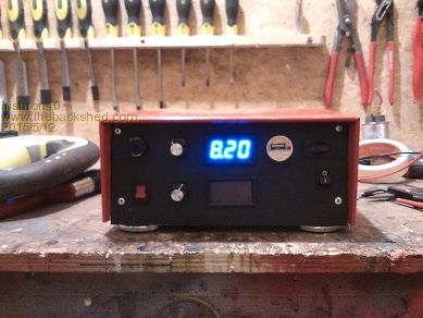
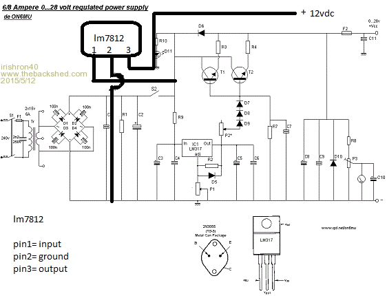
just finished building my casing and fitted all switches , fuse holders and meters.just have still to fit the output connectors I just wonder, I like a constant separate 12volt supply 
could i connect a lm7812 the way I have drawing it ? thx. ron 
|
||||
| Gizmo Admin Group Joined: 05/06/2004 Location: AustraliaPosts: 5078 |
Yes, but dont forget to add some capacitors to its output. Voltage regulators need caps on both the input and output or they wont work correctly. Glenn The best time to plant a tree was twenty years ago, the second best time is right now. JAQ |
||||
| irishron40 Senior Member Joined: 22/09/2014 Location: IrelandPosts: 251 |
what type of uf caps would i need for output. or is that not important glenn? thx ron |
||||
| Gizmo Admin Group Joined: 05/06/2004 Location: AustraliaPosts: 5078 |
I would use a 10uF 25v electrolytic, plus a 0.1uF greencap. The best time to plant a tree was twenty years ago, the second best time is right now. JAQ |
||||
| irishron40 Senior Member Joined: 22/09/2014 Location: IrelandPosts: 251 |
ok thanks glenn. I will use those. ron |
||||
| irishron40 Senior Member Joined: 22/09/2014 Location: IrelandPosts: 251 |
just thinking glenn, am I not right in thinking that I should try and keep capacitor voltage rating as close as possible to the output, so would a 16v not be better then a 25v? forgive me for questioning your expertice, but I was just thinking as the 7812 wont give out more then 12v . ron |
||||
Downwind Guru Joined: 09/09/2009 Location: AustraliaPosts: 2333 |
A capacitor voltage rating higher than the output voltage of the 7812 will make no difference to operation of the capacitor, in actual fact its better to have a higher voltage rated cap, the only down side is they are normally larger in size and cost a fraction more. The voltage of a cap is not important as long as it is rated higher than the working voltage, it is the uF rating of the cap that is the important part. Pete. Sometimes it just works |
||||
| Gizmo Admin Group Joined: 05/06/2004 Location: AustraliaPosts: 5078 |
Yeah Pete's spot on, you can use a cap rated at any voltage higher than its likely to see. The cost and size of the cap will increase along with its rated voltage. For 12v circuits I generally use 16v caps, but in your case, its a power supply and there are unknowns. If you were to accidentally connect a 24v battery to its output, or the output was introducing spikes, then a 25v cap give a better safety margin. If a cap experiences reverse or higher voltages, it can go pop and make a mess with bits of paper and aluminium going everywhere, its a bugger to clean up. The best time to plant a tree was twenty years ago, the second best time is right now. JAQ |
||||
| irishron40 Senior Member Joined: 22/09/2014 Location: IrelandPosts: 251 |
so if i need a 330uf cap. i could use a 400volt one? also i wonder. i was looking for 47nf caps and found green ones and red ones. is the only differents in those temp ratings? or manufacturer? they only shows uf and nothing else im am learning every day . lol thx ron |
||||
| Gizmo Admin Group Joined: 05/06/2004 Location: AustraliaPosts: 5078 |
Dont confuse uF and volts, very different things. A 10uF 16v cap has a capacitance of 10 uF, or 0.000001 farads. The volts is the max continuous voltage that cap will work at. A 10uF 25v cap is still a 10uF cap. The best time to plant a tree was twenty years ago, the second best time is right now. JAQ |
||||
Downwind Guru Joined: 09/09/2009 Location: AustraliaPosts: 2333 |
If i remember correctly the green caps are rated to 100v and the red ones to 400v, but in your case you could use almost any cap with a 47nF rating as almost all caps of that size have a voltage rating of 50v or above. I like monolithic caps or polyester caps as they are small with good leg spacings, but green caps work just as well. Pete. Sometimes it just works |
||||
| Page 1 of 2 |
|||||