
|

|
Forum Index : Electronics : Variable bench power supply circuit
| Page 1 of 3 |
|||||
| Author | Message | ||||
Downwind Guru Joined: 09/09/2009 Location: AustraliaPosts: 2333 |
This circuit is for a variable bench power supply, up to 10 amp and a Maximum 40 volt DC input. It might not be as good as Oztules PSU supply hack. I have had this circuit in use now for over 20 years and has never let me down and is one of the most handiest gadgets i have built. It is based around a LM-723 voltage regulator chip and has current limiting. LM-723 Data sheet here Very handy. I often end up with the power clips shorting out on the bench and with no problems. The 2N3055 transistors are a well proven high current transistor although a rather old type now. The transistors will need to be mounted on a good size heatsink. The bridge rectifier can also be mounted on the heatsink to. For this reason i mount them off the board and wire to them. The capacitor bank on the input side can be changed to a single large cap if you have one suitable. The 5 watt resistors will run rather hot under high load and need to be mounted with air flow around them. I have often soldered them direct to the pin of the transistors with the other leg commoned together and wired back to the board. When purchasing the 2N3055 transistors ask for them to be all the same batch number as this will help eliminate internal differences. The pot values shown might need to be changed to allow adjustment over the desired voltage range and current limiting range. A test with the output leads shorted together will soon show max current settable range. A suitable transformer for the amps required will be needed. It is a simple circuit with a hand full of components. The only need for a pcb is for the LM-723 and the 3 small resistors and 2 caps. The rest is mounted to the heatsink or front panel and wire connected. 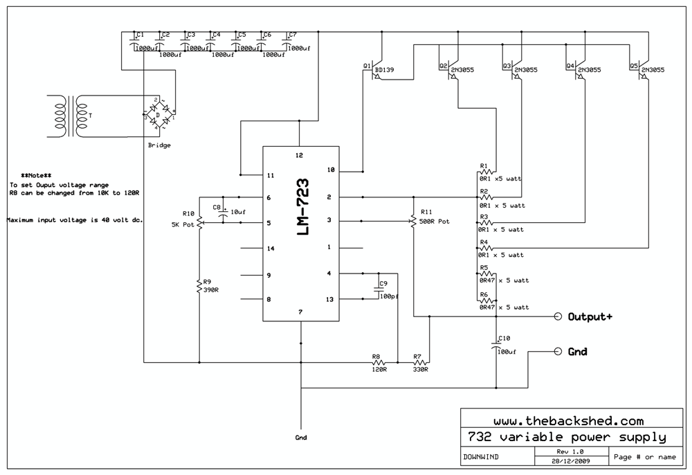
2010-01-25_021539_LM_723_variable_supply_schematic_in_PDF.pd f Pete. Sometimes it just works |
||||
| Gizmo Admin Group Joined: 05/06/2004 Location: AustraliaPosts: 5078 |
Thanks Pete, thats a circuit I'll file away for the next time my variable power supply blows up. I've used the 317T voltage regulator for as long as I can remember. My current supply uses a 317 driving a couple of 2N2955's, each driving 3 2N3055's. It's ok so long as you dont short the output. But shorting the output is something I do regularly 
One little trick I recommend is using 2 adjustment pots. A coarse adjustment, the 5k pot, and a fine adjustment, say a 500r pot in series with either outer leg of the 5k pot. It comes in handy when working on gear thats meant to monitor voltage, like a windmill controller. Glenn The best time to plant a tree was twenty years ago, the second best time is right now. JAQ |
||||
| Tonda Newbie Joined: 16/11/2009 Location: CanadaPosts: 8 |
Hello Pete, I' will buid this power supply when I get LM723. I have couple of questions.1. Where is R11 mounted? would small trimmer control on PCB do? and 2. BD139- does it need a heat sink or is it OK to solder it to PCB only? Thank you sir for your help. Kind regards, Tony at www.radiodoctor.org 
Tony |
||||
Downwind Guru Joined: 09/09/2009 Location: AustraliaPosts: 2333 |
Hi Tony, What i done was mount both R10 and R11 on the front panel so i could adjust the current if needed and adjust the voltage. There is no reason R11 cant be mounted on the pcb and the current set to a level a bit lower than the rating on the transformer, then a small trimmer would do fine. You might need to play with the values of R10 & R11 to get a output range suitable to your needs. The BD 139 can be mounted anywhere and should not need a heat sink. I just found it easier to screw it to the heatsink along with the 2N3055's I will post a pdf of the schematic here soon as it will make it easier to print off and clearer to see. Its a good power supply circuit and has served me well for many years. Put the LM723 chip on a ic socket as should you damage it by some silly fault it is easier to flick out and replace. I did kill mine once by connecting a big battery in reverse and took out all the 2N3055's and the LM723. Otherwise its been faultless in operation. Pete. Ps. Link to PDF schematic is now under the picture above. Sometimes it just works |
||||
| Tonda Newbie Joined: 16/11/2009 Location: CanadaPosts: 8 |
Thanks Pete, I just finished building it today. I had power supply with LM 317, like Glen. I kept blowing 2N 3055 weekly. So I just changed the IC into 723 and it works, shorts do not blow it any more! So far I get only 10 volts max. out of it, but I overlooked  your note about the value of R 8. That should do it, I think, I had 30 Volts before with LM 317. I spent hours checking for goofs but found none, I will play with R8 to get my voltage up. your note about the value of R 8. That should do it, I think, I had 30 Volts before with LM 317. I spent hours checking for goofs but found none, I will play with R8 to get my voltage up.
Thanks again, 
Tony Tony |
||||
Downwind Guru Joined: 09/09/2009 Location: AustraliaPosts: 2333 |
Hi Tony, Once you get your voltage range sorted you will have a great bench supply and a lot less bad words on a weekly basis. 
I built some for use in trucks for a stepdown from 24v to 12 as they kept blowing up the bought power stepdowns at a excessive price.(he had spent $1000's over the years) Now if it gets shorted out or overloaded no problems. The owner was amazed when i shorted the outputs together to show him and could only say $$$$$$$$$ in the past. Perhaps you could post the actual resistance used to get your required voltage out when sorted as i was to lazy to pull my supply apart to see what i used long ago. Pete. Sometimes it just works |
||||
| Tonda Newbie Joined: 16/11/2009 Location: CanadaPosts: 8 |
Thank Pete, I worked on it tonight, and replaced R8 1k for 150 ohms and now it delivers 2-24 volts, no problem! I have current limiter trimmer set at 15A (it can deliver 20A) but my A-meter range is only 15A. 
Thanks again, 
Tony at www.radiodoctor.org Tony |
||||
Downwind Guru Joined: 09/09/2009 Location: AustraliaPosts: 2333 |
I have changed the value of R8 in the schematic above to 120 ohm. This should allow for 24-28 volt range to be meet. Thanks for the feed back. Pete. Sometimes it just works |
||||
Downwind Guru Joined: 09/09/2009 Location: AustraliaPosts: 2333 |
In response to another thread on this power supply i will add some photos of the original one i built over 2 decades ago and still use today. It was constructed back when my electronic skills and abilitys were a lot less than they are today and upon opening the enclosure for the first time in over 15 years it was a trip down memory lane of what was inside. When it was constructed i used 2 seperate power supplies and seperate voltage regulators 1 being the LM-723 as per detailed above and the other a LM-317 for lighter applications where i needed two different voltages. Over time the LM-317 has died (or more like been killed) and had never really found a use for the need for 2 supplies, so would not recommend the need for the LM-317. The heat sink was salvaged from some other appliance but i dont remember what it was. Although the supply will go to 10 amp the amp meter is only 5 amp and has spent some time at FSD but rearly there is a use for more than 5 amp. A 3rd small (tiny) transformer was also used to power the LCD display as it could not use a common supply to the voltage being monitored. 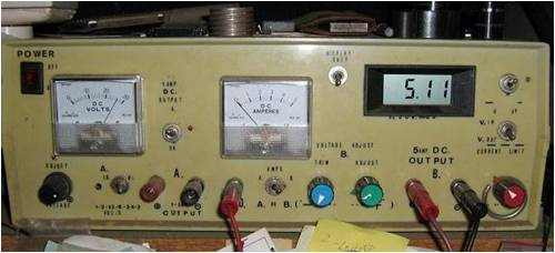
Heres a view of the rats nest inside 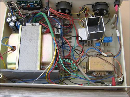
The heat sink is rather large but it was what i found when constructing the supply 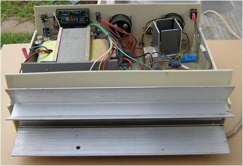
The transistors are all mounted on the outside with their legs protruding into the box. 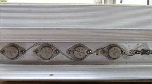
The bridge rectifier is also mounted through the back panel onto the heatsink. 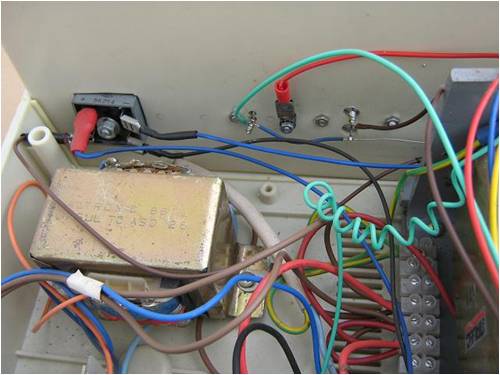
The main circuit with the LM-723 was crammed onto a small pcb with the 5 watt resistors and capacitor filtering mounted vertically. Not the neatest work i have done. 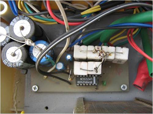
This is the 1/2 of the front panel that relates to the 10 amp power supply. 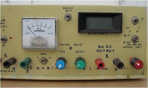
I have used 2 pots in series for voltage ajustment (blue and green) as one acts as the main full scale adjustment and the second as a trim adjustment for fine tuning applications like setting up a voltage controller. The red knob is for setting the maximum amps output and for most test work it pays to set it low so if a circuit problem is evident the current is limited and often the magic smoke is retained in the circuit. There is switches for reading voltage in to the display from a circuit, but never used it and is a waste of time adding it. The binding posts for the banana plugs is for power out and are handy to be able to attach a multimeter probe to from time to time. The green binding post is connected to the mains earth for a ground point but never really used. A greed led shows when the output is switched on and is a very handy indicator. This is fed by a seperate supply used for the lcd meter and switched with the second half of a DPDT toggle switch used to control the DC output. A power cable with aligator clips on the end make up the power out cable. Thats it!! Pete. Sometimes it just works |
||||
| readyakira Senior Member Joined: 17/07/2008 Location: United StatesPosts: 114 |
Hey Dw, do they make those 3055's in a flat style? The HS I got is not a very good type for that package. I will try to post some pics of it as well as the amps that were in that kenwood the are 2sa1215 looks like they were made by a company called sanken??? Anyways I will try to get a few pics of some of the ones I have. Don't you think Free/Renewable energy should be mandatory in new buildings? |
||||
| readyakira Senior Member Joined: 17/07/2008 Location: United StatesPosts: 114 |
This is an image of the power amps out of that box. There ae 4 of them. 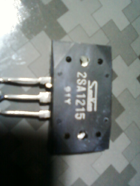
This is a pic of the bridge rectifier out of it. It has the heatsink built into it. The 50v 25a ones I have don't. I wonder how many amp this one can handle. 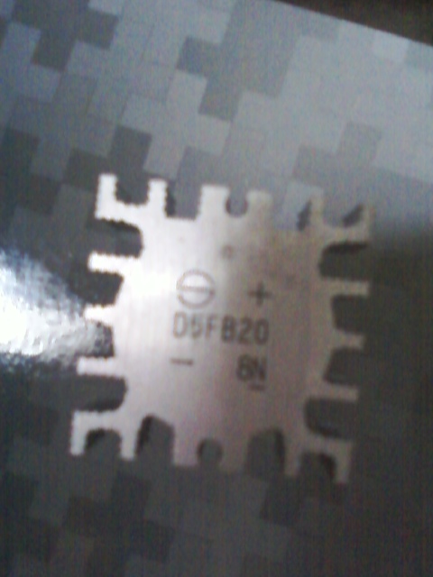
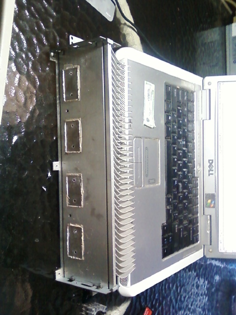
Here is 2 views of the Heatsink. This is why I asked about different power amps. Notice the 3055's can't be installed to this without major modding to the heatsink. 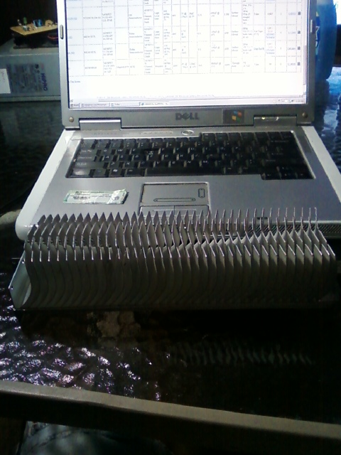
And lastly what the heck is this thing? 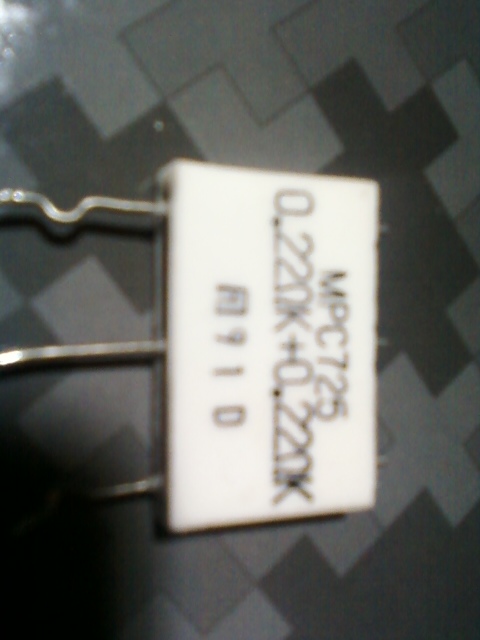
It looks like some sort of double resistor? I haven't thrown a dmm on it yet, but am going to after I look at this xformer from one of the pieces to see the output voltage. Don't you think Free/Renewable energy should be mandatory in new buildings? |
||||
Downwind Guru Joined: 09/09/2009 Location: AustraliaPosts: 2333 |
Hi Ready, Yes they do make a transistor in a flat pack and one part number is MJE-3055T its in a TO-220 package. The What the heck?? question ....is a double 0.22 ohm ceramic resistor (proberly about 5 watt) with the centre leg common to both resistors. Try using Datasheetcatalog.com to look up the part numbers It is free to use and a very good site for finding data on stuff. http://www.datasheetcatalog.com/ If there is dashes and spaces in a part number leave them out when you enter the number in the search window.....enter all digits in one string. I had a look and did not find the rectifier with the number shown in the photo. The heat sink looks more than enough and could be under half that size, but like me we use what we have as its cheap. The transistor you pictured is a PnP type and not much good for this build. Heres the data sheet on it. http://www.datasheetcatalog.org/datasheet/mospec/2SA1215.pdf Pete. Sometimes it just works |
||||
| Gizmo Admin Group Joined: 05/06/2004 Location: AustraliaPosts: 5078 |
I see the latest edition ( June 2010 ) of Silicon Chip magazine has a Dual Tracking 19v Power Supply project. Its based on a LM317 and its negative rail version LM337 regulators, and a whole lot of op amps. Glenn The best time to plant a tree was twenty years ago, the second best time is right now. JAQ |
||||
| jsteve126 Newbie Joined: 13/08/2010 Location: JapanPosts: 1 |
Downwind, I'm currently putting together a power supply based on your schematic. Looks good. I've managed to find some formulas to spec vmax, vmin, imax etc. But, I'm not sure how R5 and R6 are calculated. Would you be able to clarify? Thanks |
||||
Doug Regular Member Joined: 11/05/2010 Location: New ZealandPosts: 41 |
Hi all. Just been reading about Pete's power supply. Not being very experienced in electronics, I decided to Google the 2N3055 transistor to find out more about it. I clicked on images and came up with an amazing array 2N3055 based circuits. A lot being various types of power supplies. One circuit that caught my eye was for a resettable electronic fuse. With so many possible uses I thought you all might like to take a look at it, so here's the link (I hope, ha ha) Doug http://electroschematics.com/2923/dc-electronic-fuse/ fixed it for ya. May The Power Be With You |
||||
Doug Regular Member Joined: 11/05/2010 Location: New ZealandPosts: 41 |
OK, try this. http://electroschematics.com/2923/dc-electronic-fuse/ May The Power Be With You |
||||
Doug Regular Member Joined: 11/05/2010 Location: New ZealandPosts: 41 |
Cool, Thanks Glenn. Doug May The Power Be With You |
||||
Downwind Guru Joined: 09/09/2009 Location: AustraliaPosts: 2333 |
Hi jsteve126 R5 & R6 act as a current shunt to allow for the current limit to be set for the LM-723. R5 & R6 could be any low value resistor that will handle the current rating of the supply you are building, and for interest they could be replaced with a analog amp meter and the internal shunt of the amp meter used instead of R5 & R6. The value of R5 & R6 might limit the range of setable current limiting, and at present with the values shown i think it will allow for a minimum of 3 amp up to a max of 10 amp to be set. Its been too long since i built this circuit to remember clearly now. By increasing the shunt resistance slightly should allow for a lower minimum amp setting to be acheived. You might need to do some testing to decide on the correct value to suit your needs. Just remember the higher the resistance the more power that will be lost in the circuit and the higher the temperture the resistors will operate at. Pete. Sometimes it just works |
||||
| jgarnold Newbie Joined: 04/10/2010 Location: United StatesPosts: 8 |
I recently learned how to use the EAGLE schematic drawing software, so I redrew the original poster's schematic to make it easier for me to understand. I also spent a number of hours learning how all of the resistor values are calculated. There are many LM723 based schematics available on the net, but nobody seems to fully explain how all of the component values were selected. 
Here's how to calculate the resistor values... The above schematic was designed to be a variable 2-30 volt and 1.25-5.0 amp power supply. So, the voltage is adjustable over a 15x range and the current is adjustable over a 4x range. The first values to calculate are R2 and R3 which control the high end of the voltage range (30 volts). These two resistors form a voltage divider that is connected to pin 4 of the LM723. The internal reference voltage of the LM723 is 7.15 volts, so you need a voltage divider that will divide 30 volts down to 7.15... (30 / 7.15) = 4.19 or (30 / 4.19) = 7.15 You need to find a set of two common value resistors that will divide 30 by 4.19. I used R2 = 15K and R3 = 4.7K. The formula for a voltage divider is ((R2 + R3) / R3), so if we plug in our two resistor values, we get... (15K + 4.7K) / 4.7K = 4.19 (perfect match!) The next resistor to calculate is R1. This resistor along with the V-COARSE 10K potentiometer forms another voltage divider that determines the low end of the voltage range (2 volts). It divides the internal reference voltage available on pin 6 and feeds the resulting voltage into pin 5. Since the ratio of the high end voltage (30V) to the low end voltage (2V) is 15:1, you need a voltage divider that divides by 15 when the pot is turned completely counter-clockwise (you can ignore the V-FINE pot for this calculation since its value is zero when turned completely counter-clockwise). I selected values of 10K for the pot and 750 ohms for R1. Using the voltage divider formula again, we get... (10K + 750) / 750 = 14.33 (not 15, but close!) This will result in a low end voltage of approximately 2.1 volts (30 / 14.33). You could attempt to use a different pot and/or resistor to get closer to 15 (and 2 volts), but you'll probably end up going around in circles, especially since pots only come in a small number of values (1K, 5K, 10K, etc). 750 ohms is the common resistor value that gets you closest to 15. I'll describe how to determine the values for the R6 and R7 current limiting resistors in another post. These are a little more difficult to explain and understand. -Jeff |
||||
| dwyer Guru Joined: 19/09/2005 Location: AustraliaPosts: 574 |
HI Jeff Welcome to this forum and l do like your schematic drawing and find very simple to built however i got heavy duty transfomer deliven 30 volt 15 amp and wondering if this able to take 15 amp instead 5 amps ?? 
regard Dwyer |
||||
| Page 1 of 3 |
|||||