
|

|
Forum Index : Electronics : Battery overvoltage protection options for poida MPPT?
| Author | Message | ||||
| flyingfishfinger Senior Member Joined: 12/09/2020 Location: United StatesPosts: 110 |
Hello folks- I think this merits its own thread, but if people disagree I can make a post on the MPPT thread. Story time first though, then we can talk about fixes or solutions... When I visited my site a while back, we found a catastrophic situation at-hand. I am unsure of the sequence of events or what caused it for sure, but the end result was 4 blown batteries, a shorted FET on the MPPT, a fried Xantrex 4kW inverter and battery acid in my power closet. In the summer, my power closet faces the sun. In the afternoons, it get quite toasted for hours in direct sunlight, but it is (normally) well insulated and cool inside. When we got there this time though,the doors were wide open for what might have been weeks. This exposes my (black) deep-cycle batteries to the sun, and I'm sure they could easily get extremely overheated. Here's what they looked like: 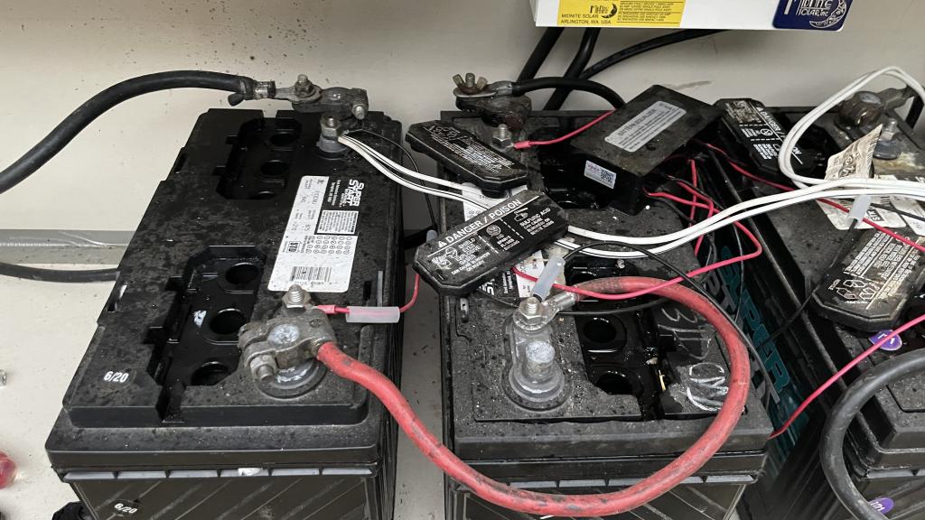 The valves are literally blown off the left-most battery, and you can see acid splatters on the wall behind it. According to my dad, on the other two batteries visible the valves didn't blow completely off but were loose, as if they had just barely popped. My solar array puts out about 127V at MPPT. When we arrived, this is what we saw on the screen: 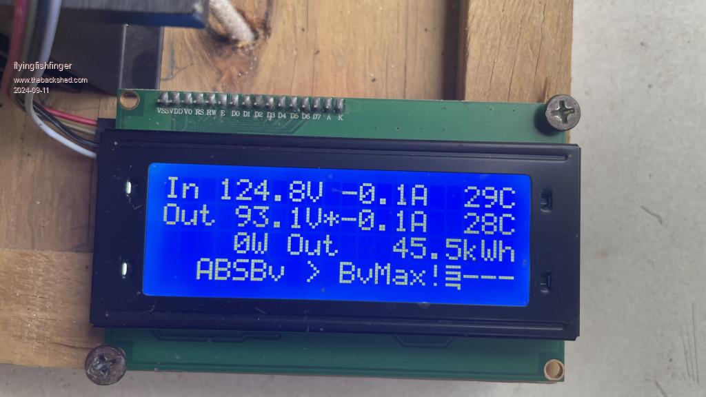 The way I read this is that the batteries are totally overcharged / destroyed and hanging out at 90V, and because I found a blown FET on the MPPT the input is connected directly to the output. My dad didn't know this, and since we had no cell network at the time he flipped on my inverter without checking....BOOM. That's my best reading of the sequence of events, although I can't say whether the FETs fried first, overcharged the batteries, blew the valves, or if the heat boiled the batteries and made their resistance so high that the voltage shot up, and that popped the FET. That's my first question... Second question: What kind of high-current overvoltage protection can we built / implement to cut off the batteries or MPPT from the rest of the system, if this kind of thing were to happen again? I can buy a pair of fancy contactors such as these , with a voltage-based trigger circuit, but those are kind of pricey. What other things could we do here? I decided this was a good time to invest in a set of AGMs to replace what I had, so hopefully I can make those last and protect them. Still not sure how bad the Xantrex is blown, I need to take a look at it in detail. For sure some of the driver board control circuitry is smoked (resistors and caps), but I didn't measure the FETs yet... Cheers, R |
||||
| poida Guru Joined: 02/02/2017 Location: AustraliaPosts: 1416 |
I agree, this needs to be looked at and solutions found. wronger than a phone book full of wrong phone numbers |
||||
| andymc70 Regular Member Joined: 30/06/2019 Location: AustraliaPosts: 43 |
Hello Poida Didn't the crowbar circuit solve this issue with my mppt's? Andy |
||||
| -dex- Regular Member Joined: 11/01/2024 Location: PolandPosts: 99 |
Check out my thread, I had the same problem. Fortunately, I was with the batteries when the MPPT was applying full voltage from the PV panels. Yes, I used something like 'fancy contactors' and a simple comparator circuit. Another cheaper but one-time solution is a scr crowbar with an appropriate fuse. Edited 2024-09-12 02:41 by -dex- |
||||
| mab1 Senior Member Joined: 10/02/2015 Location: United KingdomPosts: 209 |
My default is diversion controllers. Part of that is i have a hydro-electric generator, and whilst they are less adverse to running unloaded than wind generators, it's still better to divert surplus power than unload the generator. 2nd reason is i use several grid tie inverters due to their being cheap mppt option and their long range ('high' voltage) transmission abilities - but they don't stop when the battery's full. 3rd is that i live in a 'cool' (temperature wise) part of the world and for much of the year excess energy can usefully be turned into heat. So my 1st diversion is the hot water immersion, the 2nd and 3rd are storage heaters in the house, 4th is a big storage heater in the cowshed (during midsummer it can be hot enough for me to not want the house heated), and the 5th is a big resistor in the electrical shed where the batteries and inverter are - in theory this one should never come on - but it's there 'just in case'. Each of the diversion controllers is independent of the others, 1, 2, 3 and 4 are a.c. and the 6th is d.c. so if the a.c. goes off there's only one diversion controller, but that one is big enough to handle any of the mppt controllers for d.c. coupled pv plus the hydro, and of course the gti's will shut down without a.c. There is another d.c. diversion controller but i managed to blow it up so it's in the to-be-repaired pile (but as I'm planning a transition to 48v with wiseguys inverter, it may be repaired as a 48v unit). |
||||
| nickskethisniks Guru Joined: 17/10/2017 Location: BelgiumPosts: 458 |
Unfortunately you were not the first to experience this problem. You could see it as a flaw or lack of feature in this case, so there is a need for extra external protection layer. Lot of work was done to make this a very robust controller (my first controller was put in service end 2019 without problems) but under other circumstances, very high currents, up to 80-100A for longer periods but much less voltage ( <75V). I think this higher voltage you and others use might not been tested enough (with tested I mean a complete analysis like poida did with an oscilloscope and stuf, but important it was done with certain silicon and with lower voltages). Allthough I'm convinced this is perfectly usable with higher voltage panels. The controller is now on a smaller array since I went for newer panels and choose to build a triple controller. I had a big contactor that could disconnect the dc but I could not use it for 3 different arrays. It consumed at least 5-10W and did not want to tripple that, those are also expensive so I came up with something different, but not cheap either. I use mosfets to disconnect each solar string, a few mosfets parallel and in antiseries, so it could disconnect DC bidirectional without lot of energy loss. They are controlled by a 24V signal comming from my domotics system, but could be controlled by a simple opamp or arduino sensing the voltage. (I do not know why the pictures are not the way I want...) 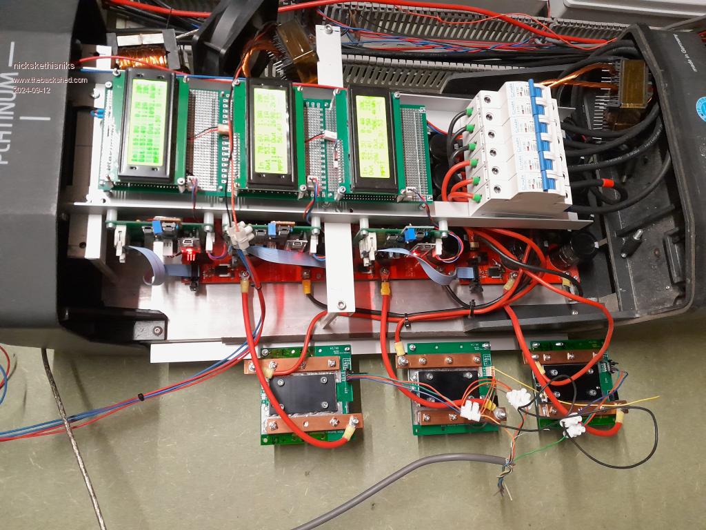   Edited 2024-09-12 05:39 by nickskethisniks |
||||
Revlac Guru Joined: 31/12/2016 Location: AustraliaPosts: 1020 |
I was looking at a Shunt Trip release, however most of them are for AC circuit tripping, but the I like way it works. What I'm thinking, I have one of those A30 controllers for over voltage detection etc, and Have an old DC rated 65A circuit breaker from a battery charger that can be connected to the solar charger input, it has a small hole in the top of the switch leaver so a wire can be inserted, I could use a solenoid to pull the breaker to off position, when battery over voltage is detected by the controller and this will cut off the solar input to the charge controller, its a bit agricultural, and mechanical but should be reliable , there is more to this just haven't worked it all out yet.  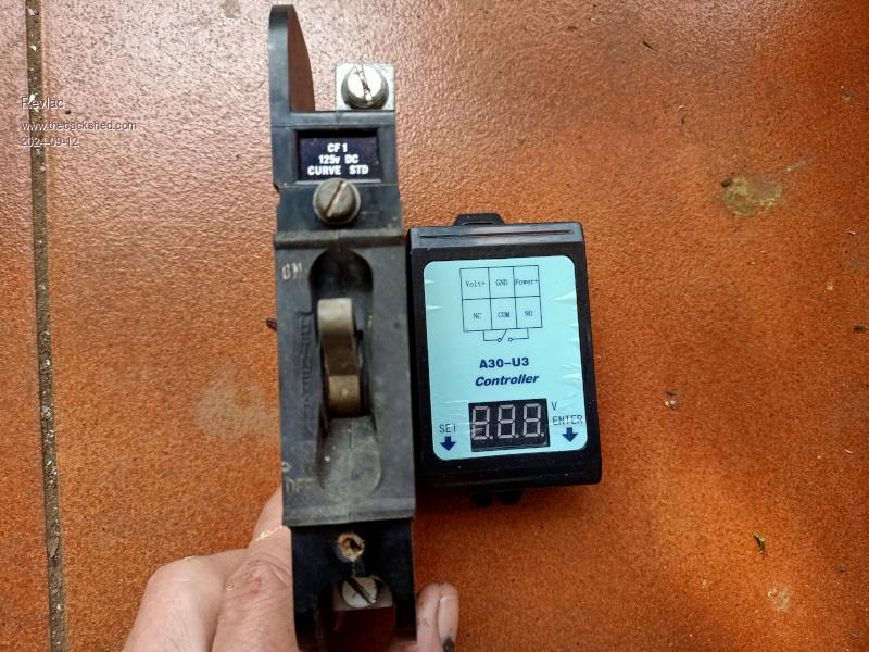 Cheers Aaron Off The Grid |
||||
| flyingfishfinger Senior Member Joined: 12/09/2020 Location: United StatesPosts: 110 |
Which thread, please? Oh yeah I'm not faulting the design whatsoever. It's great, easy to service and diagnose. I replaced the FET onsite in the middle of nowhere with a super basic soldering iron and put it right back into service! I had just replaced the FETS with a higher-voltage version, no issues there. For "simple" solutions, I feel like the contactor + comparator would be good. I would put one between the MPPT and batteries, and another between batteries and inverter (the latter does have the main load DC breaker too). However, the load-side one would need to support 100A and those are even more pricey ($46 USD at Digikey) than the 40A one I linked above for the MPPT-side ($35 USD). That's a small price to pay for protecting the rest of my system (and sanity), but if there are cheaper solutions that are bomb & idiotproof I'd love to discuss them. Cheers, R |
||||
| KeepIS Guru Joined: 13/10/2014 Location: AustraliaPosts: 1679 |
The Kilovac relays are rated at 900V and 500A, get one with the economizer, they draw 1 or 2 watts energized, come in 12v to 24v OR 48v to 72v versions. As little as $37 USD from China, don't like China, then pay $100 to $500, some crazy pricing around at the moment, all of mine have worked perfectly tripping at currents over 500A peak at 53V. It's all too hard. Mike. |
||||
| -dex- Regular Member Joined: 11/01/2024 Location: PolandPosts: 99 |
Here I see that we are both using higher PV panel voltages than originally tested. Input capacity may be important to. In my case I ended up using SiC diodes and haven't experienced MPPTs failure since then. |
||||
| flyingfishfinger Senior Member Joined: 12/09/2020 Location: United StatesPosts: 110 |
Thanks. I see that you made this. How did it work out for you? Maybe I should make one too. I also found, through your thread, that this is still good - perhaps I'll grab a couple. These seem like a good start. I have also run into the precharge problem, I didn't have a suitable high-wattage resistor on hand last time I disconnected my batteries so I had to the the hit (sparks) on reconnection. What did you end up doing for that? Cheers, R Edited 2024-09-12 19:26 by flyingfishfinger |
||||
| -dex- Regular Member Joined: 11/01/2024 Location: PolandPosts: 99 |
Yes, I use this circuit, maybe some values have been slightly changed for better tuning. This is double protection, there is a transil diode there which was supposed to be the last line of defense, if by some miracle the comparator circuit failed, then D1 works and blows the fuse. During tests it turned out that using a transil even for higher voltages ratings, it reacted too quickly in case of transients and caused random fuse blowing, so I use it without D1. The circuit has some delay. I use a relay similar to the one in your picture. The precharge circuit is a monostable rocker switch feeding the voltage from the battery to the MPPT output via a 100R/3W resistor, I press for about ~4s and the caps are charged, certainly not fully, but enough to safely turn on the relay. Edited 2024-09-12 19:42 by -dex- |
||||
| flyingfishfinger Senior Member Joined: 12/09/2020 Location: United StatesPosts: 110 |
Once triggered, how are you reactivating the circuit? Are you just manually reconnecting this circuit or is the power switch on the photo of your box just not in this schematic? R Edited 2024-09-17 06:36 by flyingfishfinger |
||||
| noneyabussiness Guru Joined: 31/07/2017 Location: AustraliaPosts: 512 |
I use one of these , it has programmable voltage trip point and time it's tripped for. I have mine set for 2 secs, so it trips then counts to 2 and re-engages the relay. A decent dc relay will suffice, as mine is hooked up to the ac side of my OGI's it's real easy... I think it works !! |
||||
| -dex- Regular Member Joined: 11/01/2024 Location: PolandPosts: 99 |
There is an on/off switch at the power input, not shown in the diagram. If the circuit will be triggered, it will remain in this state until it is turned off by on/off switch. |
||||
| flyingfishfinger Senior Member Joined: 12/09/2020 Location: United StatesPosts: 110 |
Is it safe to connect PV before batteries? I always do battery, then PV... otherwise you get PV at the BAT+ (very high) until a load is applied, and the MPPT only catches up once a minute so you are dumping the PV short circuit into the batteries. Also, if PV is connected but the battery is not, then the controller is still charged up, we don't need precharge, and the controller should display "VBat > AbsMax" error. So if the overvoltage relay kicks in, then PV is still attached. We would need to cycle that too while we reconnect the batteries. Is that better or unnecessary? R |
||||
| flyingfishfinger Senior Member Joined: 12/09/2020 Location: United StatesPosts: 110 |
Built and tested a very hacky, hand-assembled version of Dex's circuit with a contactor and pre-charge. I'll put it in a nicer panel later, but I think it works ok! Late afternoon, fully shaded by trees so not much power happening. 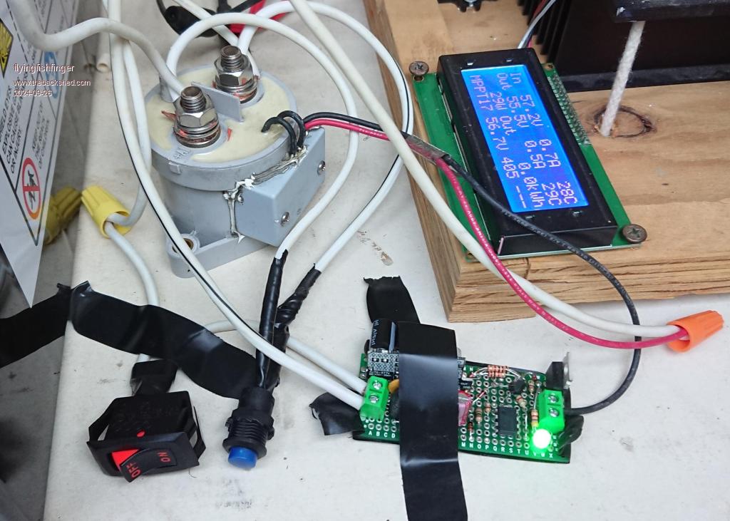 Thanks for the thoughts! |
||||