|

|
Forum Index : Electronics : data logging and monitoring of our solar power systems for anyone
| Author | Message | ||||
| poida Guru Joined: 02/02/2017 Location: AustraliaPosts: 1418 |
My home solar setup has data logged every 2 minutes. I record battery voltage, charge currents, battery temp, inverter DC current, toroid temp, etc. I think this could be generalised for other people. This is just the start of the project. Sort of a call for expressions of interest. proposed architecture: a Raspberry Pi or clone ($35 AU from Amazon for the clone) 2 x 8 channel 12 bit ADC MCP3208 1 x TTL buffer, for 5V I/O A watt meter that outputs a pulse per watt.hr Digital outputs that can be switched on or off from the website. (I have two of these. One drives the pool pump/solar heater and the other drives the 2kW battery charger, both using solid state relays) optional: USB connections to nanoverter and mppt, getting runtime data via their communication protocol. This is much easier than setting up current sensors and then bringing those signals back to the R-PI to be converted by the ADC. requirements: wired internet connection from your router a bit of commandline stuff, driven by scripts I will write. 8 GB USB stick and USB burner software you build the R-PI ADC and TTL extension card, yet to be designed. I expect to make it possible to do things like: graph all 13 voltages of a 13S Lithium battery, showing each of the 13 cell's voltages as it drives it's load. This will show early warning of failing cells It will show battery voltage, charge current, inverter running data, etc. It all depends on your requirements and what you want to measure. Analog voltages will need to be between 0 and 5V. Active current sensors will work well. The R-PI will be connected to the home LAN and it will be possible to access the graphed data from "outside" the home LAN after some fiddling with the home router. Have a look at http://1eq2.cc/mppt/datah.php to see what I use. The logger will appear like this and be customisable for various people's needs. First code tests show I can get excellent repeatability with ADC conversions using the MCP3202 ADC, a 2 channel version of the 8 channel parts I want to use. This is the result of a simple python script to record the two channels of the ADC and digitally remove lots of noise. I scale the values to 0 - 60V, to simulate the voltages from a 54V 13S Lithium battery, same as a 48V Lead Acid battery. channel 0 seems to have a little less noise. It appears we can expect repeatable measurements to within 0.01V This will be perfect for monitoring the many voltages in the series connected battery. data details: every 2 minutes a new record will be inserted into the database. Each record will have a date and time stamp, and about 25 values. (why that many? We need 13 voltages, a few temperatures, current measures, etc..) The main logging script will obtain the voltages, temps etc and then send a query to the database to insert the new record. There will be a way to define what each of these values means. This is where we assign a name to a value, and also define if it's a simple time series stream or if it's derived from other values (e.g. DC power. This will need the battery voltage and the inverter current and then multiply them to get power.) Other derived values will be energy. This is the running total of power multiplied by time. I have found the R-PI to be reliable IF you give it a stable power supply. 5V at 1 Amp is more than enough. I use a offline 5V flyback supply connected to the battery. It's always ON. My logged data now is 2,300,000 records. This is about 8 1/2 years worth. It all is stored on the 8Gb flash memory card on the R-PI. (I have backups of this data on other systems too.) I have no idea if anyone here will want to use this or just try it out for sh%ts and giggles. I suppose I need a new project. All the home system is running fine. Don't need to build another inverter. But it is time to build a better logger/system controller I will use Python as the programming language this time. wronger than a phone book full of wrong phone numbers |
||||
Madness Guru Joined: 08/10/2011 Location: AustraliaPosts: 2498 |
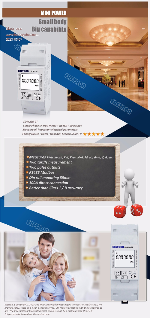
I would be very interested in this ATM I rely on the data logging of my Midnite Charge controller. However this only records it's charging and battery details. Data is uploaded once every 6 minutes to their server and can be accessed via the internet.  For me, the most important detail is the White State of Charge line. The Midnite CC counts Coulombs and has a efficiency setting for the battery to correct it for battery losses. When the battery charge changes to float the SOC is set to 100%, if the SOC was different at the time it goes to float then the efficiency setting can be changed to correct it. Would this Raspberry Pi Pico do the job? https://www.aliexpress.com/item/1005004702155130.html? ATM I also use one of these Eastron AC power meters that was previously connected to my GTI's for data logging. It works really well and has RS485 communication. https://www.aliexpress.com/item/32845403260.htm $75 AU plus post.  The manual with all the Modbus information can be downloaded here. https://autosolar.es/pdf/Manual-SDM230-Modbus.pdf Edited 2023-05-07 08:28 by Madness There are only 10 types of people in the world: those who understand binary, and those who don't. |
||||
| poida Guru Joined: 02/02/2017 Location: AustraliaPosts: 1418 |
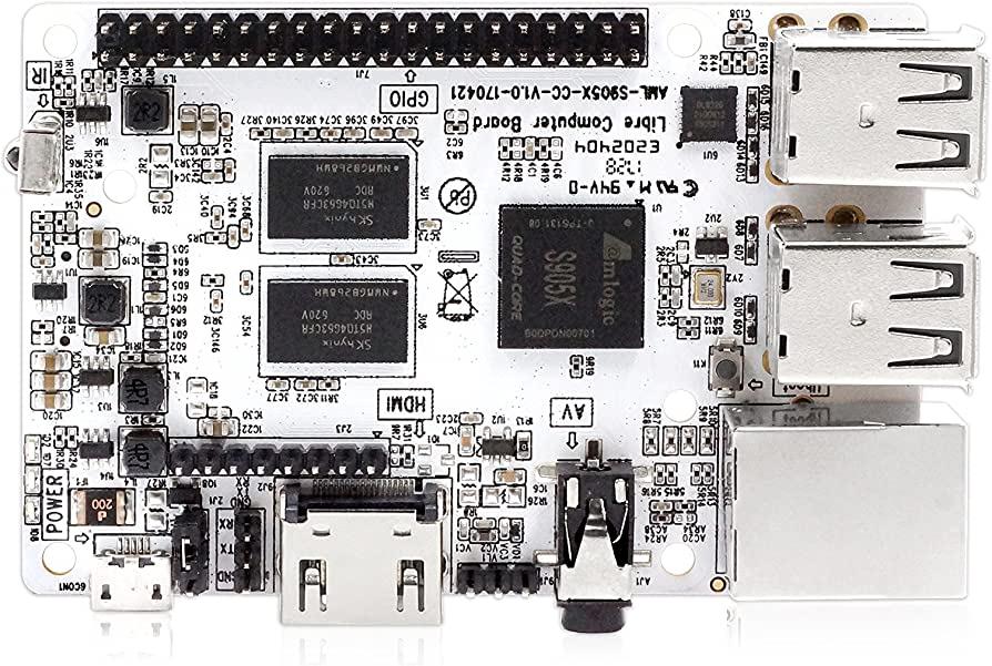
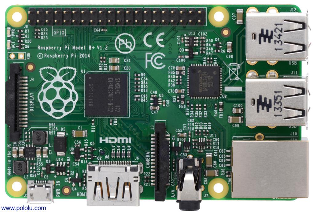
sadly, no. It needs to be something like this board which looks like this:  or a genuine R-PI. I have a few unused Model B+ versions and will develop the codes using one of those  These boards have 4 USB sockets and an Ethernet connection. I do not want to use WIFI, I find it intolerable if even a tiny amount of unreliable connection to the network occurs. With a cable it is perfect. The Eastron power meter can also be connected to the 1 Watt.hr pulse output and that is what I will use. That model meter has two outputs, one for V.A. and one for Watts. I could go the full Modbus route but then the RS-485 signal needs transceivers and you need to talk Modbus to it. Instead I just count pulses over 2 minutes. So easy. My home system uses an R-PI 3 but they are now a bit costly. Forget about the R-PI 4, hard to get and also costly. This project needs to run on cheap alternatives. wronger than a phone book full of wrong phone numbers |
||||
Madness Guru Joined: 08/10/2011 Location: AustraliaPosts: 2498 |
That Raspberry Pi is more like $70AUD with postage from Amazon, and on Aliexpress about $60AUD delivered. There are only 10 types of people in the world: those who understand binary, and those who don't. |
||||
| noneyabussiness Guru Joined: 31/07/2017 Location: AustraliaPosts: 512 |
meter hey Pete, these have a heap of features and have rs485 coms( i have one).. would it be possible to interface with a nano to send via internet to access there info?? and control em ?? it could do all the heavy lifting with actually capturing the info, columb counting included .. I think it works !! |
||||
| tinyt Guru Joined: 12/11/2017 Location: United StatesPosts: 438 |
Not sure if this Three Energy Monitor in one IC can be used. Currently available at mouser I don't know how much coding effort is needed. Edited 2023-05-07 17:31 by tinyt |
||||
| poida Guru Joined: 02/02/2017 Location: AustraliaPosts: 1418 |
Tinyt, I find it far easier to use power meters that may use ICs like this. I do not want to make a power meter at all. Just get the Eastron DIN rail meter and connect to the pulse output and count pulses. This is what I do alrady with my home system. Noneya, the meter looks interesting. Probably a bit of work getting the ModBus protocol understood. It's looking like not a lot of interest in this so let's let this die. wronger than a phone book full of wrong phone numbers |
||||