
|

|
Forum Index : Electronics : Bosch Battery Charger
| Author | Message | ||||
| larny Guru Joined: 31/10/2011 Location: AustraliaPosts: 346 |
I have several Bosch battery tools that all use the same batteries & charger. I have 2 chargers, but one failed about 2 years ago & the other one failed yesterday. I therefore want to repair them. But a circuit diagram (schematic) would be helpful. I did an internet search but found nothing useful. It is a 14.4 ~ 21.6 Volt, 1.5 A charger (see the photo). Underneath it has N153 Q061298. I searched using these numbers & found nothing. Does anyone have a circuit for this charger? Any assistance will be appreciated. |
||||
Revlac Guru Joined: 31/12/2016 Location: AustraliaPosts: 1024 |
Can you remove the cover and take some photos? My neighbour brought one around for repair, I could smell its burned inside, been wet and beyond repair. It has the same voltage as yours but only .43 Amp output, so it may be different inside to yours, different number as well. Cheers Aaron Off The Grid |
||||
| larny Guru Joined: 31/10/2011 Location: AustraliaPosts: 346 |
Here are photos of both.the PCBs. 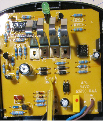 |
||||
| Pete Locke Senior Member Joined: 26/06/2013 Location: New ZealandPosts: 181 |
Can you tell us what these I.C numbers are? 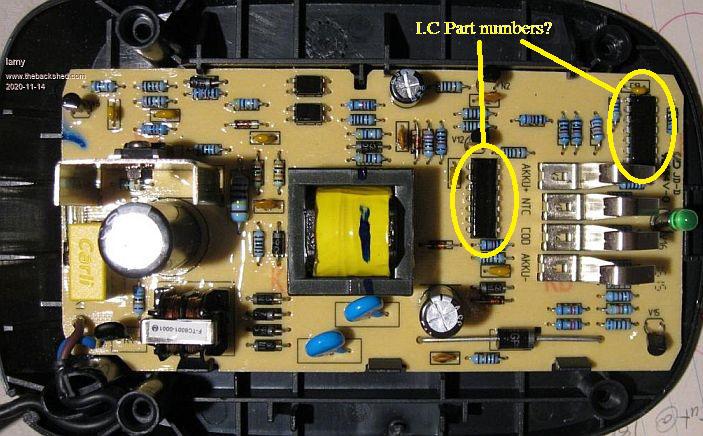 |
||||
Revlac Guru Joined: 31/12/2016 Location: AustraliaPosts: 1024 |
I have no idea about the one in the second photo, just a more powerful version by the looks of. The first one looks the same as the one here, just not as bad. 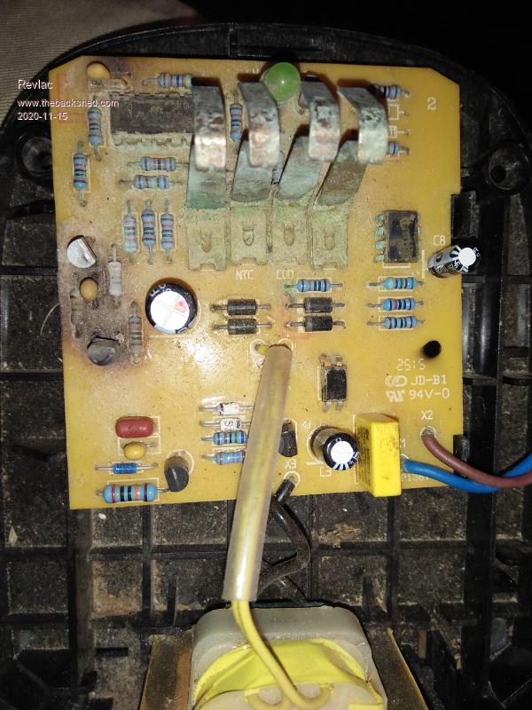 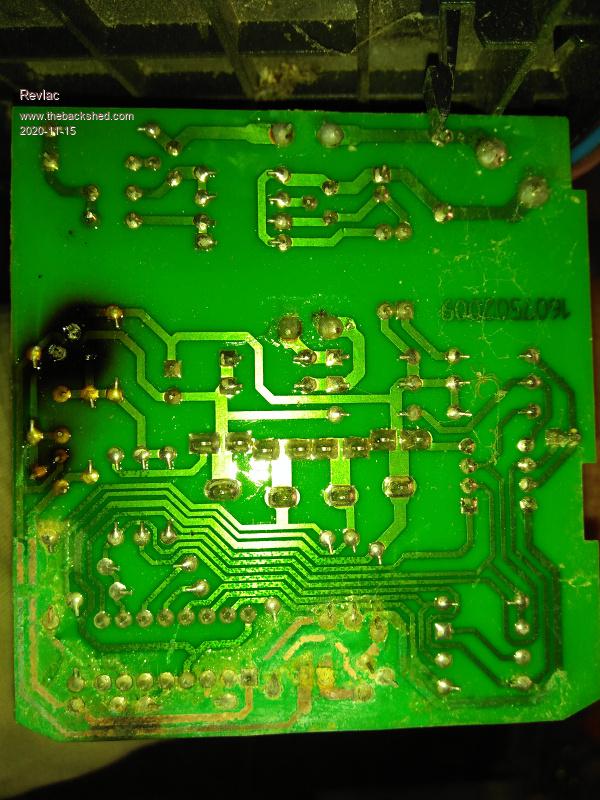 Obviously I can't help much with the component values as you can see, I looked for a schematic for this almost a year ago and found nothing either. Time to start fault finding, check for visible damaged components, dry joints then check the transformer output see if there is power then the diode bridge and so on, follow it though and you might be lucky to find something. Cheers Aaron Off The Grid |
||||
| disco4now Guru Joined: 18/12/2014 Location: AustraliaPosts: 896 |
This guy (DiodeGoneWild) on utube has some very good videos on switched mode power supplies. This one on a Bosch charger he fault finds on without a circuit. Capacitor with high ESR in the end. Look at some of the other videos to see some of his famous hand drawn circuits of switched mode supplies. I learned enough to fix my Ctek 25A battery charger for which there is no available circuit. I have two of the .43 Amp output Bosch chargers. Tried to look inside but was a bit afraid to force it open, do you just use a bit of muscle once the four screws are out. Regards Gerry Latest F4 Latest H7 |
||||
| larny Guru Joined: 31/10/2011 Location: AustraliaPosts: 346 |
Yes, the second one is higher power than the other. I did some fault finding on the first one. The output from the rectifier bridge 38.7 Volt. I had a brief look for dry joints & then decided to start this thread before doing more. |
||||
| larny Guru Joined: 31/10/2011 Location: AustraliaPosts: 346 |
|
||||
| larny Guru Joined: 31/10/2011 Location: AustraliaPosts: 346 |
|
||||
| larny Guru Joined: 31/10/2011 Location: AustraliaPosts: 346 |
The one near the transformer is a LM224 a Quad Op Amp. But the one near the LED has 2 numbers on it 5022257 & 785 1062. I did an internet search on both & had no result. So it must be a proprietary IC. The other charger also has a proprietary IC in it. That makes it difficult to see how the chargers work as I presume that much of the action is in these ICs. Thanks for the response. |
||||
| larny Guru Joined: 31/10/2011 Location: AustraliaPosts: 346 |
Thanks Gerry. I looked at the video but could not understand much of what he's saying as I have a serious hearing problem. I have hearing aids which increase the level but don't help much with the understanding. I sometimes even have difficulty understanding my wife. However, his point about the electrolytic capacitor having high ESR is a point worth considering. So I'll dig out the ESR meter I designed & built some years ago. |
||||
| larny Guru Joined: 31/10/2011 Location: AustraliaPosts: 346 |
I apologise for the repeats of the Revlac post. I was trying to quote the one from Pete Locke but I hit the wrong Quote button each time, and then stupidly saved them! I could not find anyway to delete them. |
||||
| Murphy's friend Guru Joined: 04/10/2019 Location: AustraliaPosts: 648 |
Its not your hearing, mine is good but I also have trouble understanding what's been said. Out of curiosity I checked on the type of mains socket shown (there are 15 types worldwide) and its either type H (Israel) or type O (Thailand)where the YouTube was filmed. So you were listening to somebody with a strong accent. Not understanding your wife may be a good thing at times   . . |
||||
| larny Guru Joined: 31/10/2011 Location: AustraliaPosts: 346 |
I'm afraid it is also my hearing. I have trouble understanding most people & need sub titles when watching TV. I usually need my wife to help me when someone rings me or I ring someone. It's a pain in the neck. The bloke in the video gave his URL as danyk.cz. I don't know what Israel & Thailand extensions are but cz does not seem to fit either. I thought it may be Czechoslovakia. Thanks for your interest. |
||||
| Pete Locke Senior Member Joined: 26/06/2013 Location: New ZealandPosts: 181 |
 The one near the transformer is a LM224 a Quad Op Amp. But the one near the LED has 2 numbers on it 5022257 & 785 1062. I did an internet search on both & had no result. So it must be a proprietary IC. The other charger also has a proprietary IC in it. That makes it difficult to see how the chargers work as I presume that much of the action is in these ICs. Thanks for the response. Both are on the secondary side of the supply. Can't find anything either on the second chip, guessing it's a PIC of some sort. Any chance of a close picture of it to maybe get a manufacture logo? Cheers Pete'. |
||||
| larny Guru Joined: 31/10/2011 Location: AustraliaPosts: 346 |
Both are on the secondary side of the supply. Can't find anything either on the second chip, guessing it's a PIC of some sort. Any chance of a close picture of it to maybe get a manufacture logo? Cheers Pete'. I've attached a better photo. The manufacture's logo is ST. Someone on the eda board forum said: ST means ST microelectronics, SGS, SGS Thompson. |
||||
| larny Guru Joined: 31/10/2011 Location: AustraliaPosts: 346 |
After much effort, I have drawn the circuit diagram. I presume U1 is a microprocessor but I cannot find a data sheet for it. So it must be proprietary. I found the high voltage section difficult to understand. My best guess is that on positive half cycles (where A is more positive than N) the current into C1 is set by the Opto transistor which is proportional to the current through the LED in the opto. The DIAC (E8) conducts when the C1 voltage reaches its trigger point thus triggering the TRIAC. A current therefore flows though R3, V4 & the primary of the transformer. On negative half cycles, C1 charges via D2 & C3. Again, the DIAC triggers when its trigger voltage is reached & this triggers V4. The current through R3 causes V5 to turn on which discharges C3. I don't know what the purpose of C2 is. The voltage applied to the battery is therefore adjusted by the above mentioned feedback mechanism. Any assistance will be appreciated. 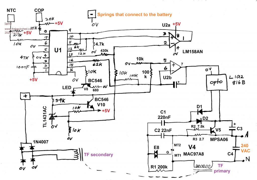 |
||||