
|

|
Forum Index : Electronics : DC bus bars
| Author | Message | ||||
| BenandAmber Guru Joined: 16/02/2019 Location: United StatesPosts: 961 |
A friend of mine has been building a inverter here at my home These inverters and solar stuff is just like drugs it's very addictive and then before you know it all your friends are doing it with you He saw my DC bus bars and I told him I wasn't going to use them Of course the question came up while I'm not going to use them It just didn't make sense to him when I told him it may make my inverter blow up I told him that I thought it had to do with the resistance going to the battery would be more than the resistance going to the inverter but I'm really not that sure myself If one of you greats on here had a little extra time I would really appreciate an explanation that is simple enough for some of us that's not so talented understand Thank you for your time be warned i am good parrot but Dumber than a box of rocks |
||||
| BenandAmber Guru Joined: 16/02/2019 Location: United StatesPosts: 961 |
I just got some very good news We will have a new member he's just waiting for the approval already signed up His name will be genetry solar He is a contractor for power jack inverters He repairs them among other things Very good honest guy I've done business with him and he bends over backwards to make you happy service beyond belief He has a channel on YouTube with lots of videos about inverters and other solar things Very good all-around guy think everyone will like him be warned i am good parrot but Dumber than a box of rocks |
||||
| LadyN Guru Joined: 26/01/2019 Location: United StatesPosts: 408 |
That is very good news. I will be delighted to have him here! |
||||
| BenandAmber Guru Joined: 16/02/2019 Location: United StatesPosts: 961 |
A ladyn do you have to have a good explanation that simple about the bus bar deal and blowing up inverters I'm pretty sure I read or somebody said it was because of the resistance being greater to the battery then to the inverter I would like to make sure my reasoning is right on this it's a question a friend of mine asked that's building a inverter This friend once owned a recycling center a pretty big one I keep on forgetting to ask him we're all the Transformers get sold to if a person could find that out might be able to get big transformers cheap be warned i am good parrot but Dumber than a box of rocks |
||||
| LadyN Guru Joined: 26/01/2019 Location: United StatesPosts: 408 |
YEAH, that would be very very helpful. I think each of us here in the U.S. are pretty much blocked from building a few Warpverters due to the lack of affordable Transformers, right? There needs to be some detailed questions to be asked about this. 1. What are you using instead of the bus bars? 2. What are the bus bars made of? 3. What are the dimensions of 1 and 2 If I were to assume you're using aluminum bus bars, I would expect their resistance to be much higher than copper bus bars. I believe their thermal conductivity is less as well. Both are bad for an efficient conductor. When I was younger I remember my brother doing jobs where he was basically helping rip out aluminum cables from walls, I think. Fire hazards could have been the reason? I will ask him |
||||
| BenandAmber Guru Joined: 16/02/2019 Location: United StatesPosts: 961 |
I know I'm definitely not going to use them I've already been warned I was just trying to get a better answer to explain to my friend Mark is the one that warned me and him and another guy had had problem The answer might already be in a post somewhere I need to figure out how to search better I just have to get it figured out people get tired of saying the same things over and over And who can blame them If you have any tips please let me know either on here or PM be warned i am good parrot but Dumber than a box of rocks |
||||
| arthur8 Regular Member Joined: 08/05/2019 Location: BrazilPosts: 69 |
I've started to follow his youtube channel since 2 months ago when i was thinking to buy some low frequency high power inverters. Nice! |
||||
| Solar Mike Guru Joined: 08/02/2015 Location: New ZealandPosts: 1138 |
There is nothing wrong with using aluminum for bus bars providing allowances are made. 1: Aluminum is 60% less conductive than copper, so to get the same current rating the conductor volume has to be 40% larger. 2: Aluminum expands and contracts with temperate more than copper, so when connections are made to it they can work loose over time; solder lugs must be bolted with spring washers to keep a constant tension on the joint to prevent a bad connection forming. 3: The oxide coating that forms on the aluminum when in contact with air is an insulator, so all joints have to be sealed, usually by some sort of jointing compound to keep the air out. The aluminum surface must be cleaned of any oxide coating immediately prior to bolting up, usually by a stainless steel brush. 4: Water must be kept away from the joint, especially when the other contact is a dissimilar metal, to prevent corrosion in the joint. So providing as a DIYer, you make allowances, everything will be fine. Cheers Mike |
||||
renewableMark Guru Joined: 09/12/2017 Location: AustraliaPosts: 1678 |
Ben, you may have been a tad confused about what I referred to when cautioning you about buss bars. Myself and John here have both experienced issues when connecting the inverter AND solar charge controller output to a buss bar that were too far away from the battery. Both of us changed our wiring to have the solar charge input direct to the battery terminals and all our problems went away. I can't remember how far John's buss bar was from his battery, but mine was around 60cm, it was connected with 90mm2 copper. I know Mad has a similar setup, but he uses a GTI to back charge a lot of his power and 5kw or so of DC input to a similar buss bar and distance from the battery. From what I have seen exceeding 8kw of DC into a buss bar of a distance of 60cm or more away from the battery will cause problems. These are just my and John's experiences. Everything I have done is with copper btw, last thing I want to do is introduce another variable. So use buss bars if you want to (for discharge), but when charging (with solar) I have found it's best to connect that charge feed direct to the battery. If you study manufacturers diagrams for charge controllers every one I have seen tell you to do it that way as well. Cheers Caveman Mark Off grid eastern Melb |
||||
| BenandAmber Guru Joined: 16/02/2019 Location: United StatesPosts: 961 |
Thanks for coming in and straightening that up a little bit  You can see this tube is pretty old My question isn't anything about the connection itself I'm just trying to figure out what is actually going on when you have your charge controllers coming into a bus bar instead of a battery I know it is an absolute fact that this is not a good practice to do I have a lot of faith in the people on this site they say not to do something I'm not going to do it My buddy on the other hand is never read this site and it sounds absolutely ludicrous to him I tried to explain to him that all wire has resistance and it must have something to do with resistance He was trying to say that you have more connections is the reason why you shouldn't do this the more connections you have the more resistant you have I told him I thought it had more to do with the resistance in the actual wire and not the resistance in an extra connection I could be wrong though and he can be right I don't know I was leaving this question for some of the great minds on here that are far superior to me and him By the way during this little argument we had I brought up that at high voltage the electricity is going on the outside of the wire and not through the inside and that really got him going We are all old best friends we did everything together growing up years ago we just recently started hanging out again All of this is in good humor and good fun I'm going to be getting him some way to get on the internet and sign him up on this site very soon He is also a best friend to staregazer We all grew up as Neighbors be warned i am good parrot but Dumber than a box of rocks |
||||
mackoffgrid Guru Joined: 13/03/2017 Location: AustraliaPosts: 460 |
I can't speak for extra high voltage, as in many kVolts, but I think you're referring to skin effect which is a function of frequency rather than voltage. I don't use a PWM charge controller, but I would have thought a buss bar ought to be fine unless it's not filtered , then you have a problem of injecting lots of noise - totally possible. |
||||
renewableMark Guru Joined: 09/12/2017 Location: AustraliaPosts: 1678 |
Exactly. I probed my DC input line at the inverter power board and saw those pulses. 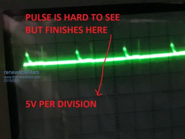 Moved connection to the battery and it didn't disappear, but it's very minimal now. So it's not really about the buss bar, it's more about what you put INTO it. Cheers Caveman Mark Off grid eastern Melb |
||||
| Warpspeed Guru Joined: 09/08/2007 Location: AustraliaPosts: 4406 |
I like to use busbars inside equipment, they are an excellent way to tie many different points together with very low voltage drops, and the busbars can also sometimes provide useful mechanical support. Heavy wiring between pieces of equipment is less of a problem where there is enough length to provide some flexibility. Very short heavy wiring inside equipment can be very stiff and place great mechanical strain on some parts, without providing any useful mechanical support. If you can bolt things such as current shunts, large electrolytic capacitors, and heat sinks directly onto busbars, it can be made very neat and compact, and very efficient. Busbars bolted directly on top (or underneath) circuit boards can provide a very effective current path between multiple high current mosfets if the whole thing is planned right. This is the last PWM inverter I made using a Chinese EGS board. Negative bus bar on the left connecting to all the mosfet sources, positive busbar on the right connecting to all the mosfet drains. If I was going to build a low voltage Warpverter using multiple HY4008s, instead of individual high voltage IGBT blocks, this would be the basis of how I would probably go about it. 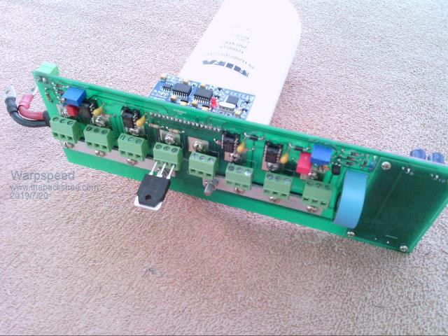 This is the other ac side, where the drains and sources of one side of the bridge pass over the top of the drains and sources on the other side of the bridge. It makes a fairly compact package, and it would be capable of carrying enormous fault currents without blowing the tracks off the board if it ever does go bang. 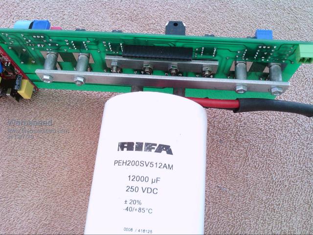 Klaus it the unchallenged busbar King with his modular Warpverter. Well worth studying exactly how he did it. https://www.thebackshed.com/forum/forum_posts.asp?TID=11461&PN=2 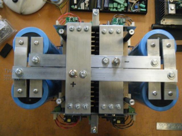 Cheers, Tony. |
||||