
|

|
Forum Index : Electronics : Stock Std Warpinverter
| Page 1 of 17 |
|||||
| Author | Message | ||||
renewableMark Guru Joined: 09/12/2017 Location: AustraliaPosts: 1678 |
OK, I'm building a standard control board for the cascade Warpinverter. Tony what is the part C19? I can't find it on the list. Also c17 is listed twice, once as a 1uf tantalum and once as a 100nf ceramic. I'm thinking that was a typo and the c17 tantalum should have been c19 as c19 is polarised on the board. 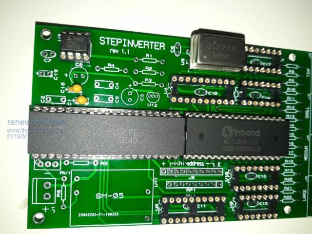 Cheers Caveman Mark Off grid eastern Melb |
||||
| Tinker Guru Joined: 07/11/2007 Location: AustraliaPosts: 1904 |
Mark, you have rev 1.1 control board there. I have the original, rev 1.0 board. That cap, C19, is marked as C25 there and is 1uF tantalum. Its across the 5V output of the DC/DC module so I guess its not that critical. Below is a pic of the board I have. 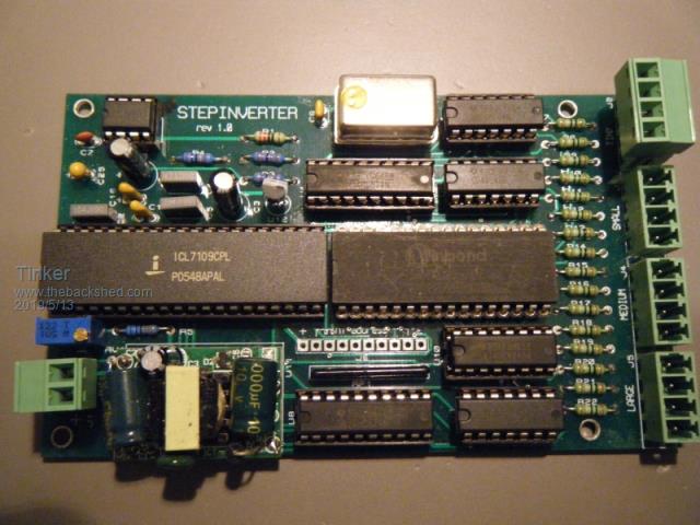 Klaus |
||||
| Warpspeed Guru Joined: 09/08/2007 Location: AustraliaPosts: 4406 |
The original Step Inverter board revision 1.0 was only ever built as an initial prototype for myself to test some rather unusual ideas that I had. I built myself one board, and to my amazement it not only worked very first go, it worked very well indeed. So I loaded a second board to use as a spare, out of the five that were made. And that was the end of it as far as I was concerned. I had a working Warpverter, and I was now off grid with zero problems, and really happy. However there were some minor details in that prototype that could have been better, but after all it was a very first initial prototype. The first mistake was that I decided to add an extra 1uF tantalum capacitor to the +5v supply when I was laying out the board. I made that C25, but it should really have been C19 as the next component designator in sequence after C18. There was also some issue with C17, but cannot now remember exactly what that was. Second mistake was the polarity of C1 which has no + sign on the silk screen. Third mistake was that the hole sizes for the screw terminal blocks were made far too large. None of these mistakes stopped it from working, and I just soldered in the components without giving it any further thought. Suddenly and quite unexpectedly people were asking for boards, so I just sent out the revision 1.0 boards that I already had, with a correct bill of materials that listed C25 as 1uF and figuring that people would work out which way around C1 had to go. I then ordered ten more boards revision 1.1 with the three errors fixed. C25 became C19 as it should have been in the first place, and is a 1uF tantalum. Whatever the issue was with C17 being duplicated was also fixed. C1 gained the missing + on the silk screen. And the hole sizes for the screw terminal blocks were reduced in size. All the tracks and pads are fine. All of the issues really only concern component designators on the silk screen (and hole sizes). I still have a few of these rev 1.1 boards and pre programmed proms available if anyone is interested. The nano boards would be a better long term solution, but if you want to get something fairly basic working initially, this is arguably the very simplest way to get started. Cheers, Tony. |
||||
renewableMark Guru Joined: 09/12/2017 Location: AustraliaPosts: 1678 |
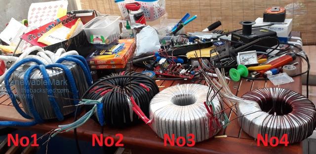 Almost finished the torroids. No1 (225v)is actually one which was all ready to go into another Madinverter. That just needs the primary wire taken off and re done with 35mm2 No 1 needs 128 turns of 4 secondaries of 2mm2 and 25 turns of 1 35mm2 primary. This is double stacked 3kw cores. I did however manage to get a hold of some more 3kw toroids, so that one may still get put aside for another Madinverter and wind another identical one for the Warp unit (but different primary winding). No2 (75v) is a 2kw core. 104 turns of 4 secondaries of 2mm2 61 turns of 13.5mm2 primary. Klaus, I think you are doing something similar here, be warned it is a tight fit. This is all I had left. 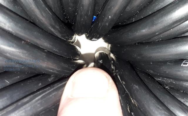 No3 (25v) is another 2kw core. 34 turns of 4 secondaries 2mm2. 60 turns of 2 primaries 2mm2 No4 (8.33v) Almost finished doing the primary. 1.5 kw core. 17 turns of 4 secondaries 2mm2 90 turns of 1 primary 2mm2. Now onto the boards. Cheers Caveman Mark Off grid eastern Melb |
||||
mackoffgrid Guru Joined: 13/03/2017 Location: AustraliaPosts: 460 |
Good one Mark.  8mm2 secondary I see, what are you going to rate this inverter at? Cheers Andrew |
||||
| Warpspeed Guru Joined: 09/08/2007 Location: AustraliaPosts: 4406 |
All the secondaries are 8mm squared, good for a nominal 32 continuous amps. At 235v that is 7.5Kw continuous rating for all the transformers combined. With a big enough battery, and enough mosfets, its going to be a real monster. Cheers, Tony. |
||||
renewableMark Guru Joined: 09/12/2017 Location: AustraliaPosts: 1678 |
Yep, what Warp said. I'm good at following instructions, not designing stuff. 1000 AH of battery it should be a bloody ripper. So far just have the little two fet boards for testing. I'll need to talk someone into helping out with the bigger fet boards. Cheers Caveman Mark Off grid eastern Melb |
||||
| nickskethisniks Guru Joined: 17/10/2017 Location: BelgiumPosts: 458 |
Wow, that's a strong table! 😁 |
||||
| Tinker Guru Joined: 07/11/2007 Location: AustraliaPosts: 1904 |
Yes, I'm fully aware about tight fits  , I had to wreck my first winding attempt because I ran out of hole space , I had to wreck my first winding attempt because I ran out of hole space  . .So, rearranged the transformers to be similar than your N0 1, then use the 2.5Kw core with the troublesome 85mm hole and modify it for No 2 transformer. It has now a 96mm hole with the removed steel placed on the outside, this cost 50mm sq of core area which = one extra wire turn. I will use a smaller secondary, 6.8mm sq total, good enough for my battery and usage. I also plan to use enameled primary wire, not sheathed cable like you. Just have to get the tiny toroid core ready yet, then the winding fun can begin. A word of warning for those wannabe warpinverter builders: 1. a set of PCB's does *not* make you a warpinverter - or any other home built inverter type for that matter. 2. these projects stand and fall by procuring the correct transformer(s). 3. I strongly recommend to any newbies tackling the transformer first, before buying *any* other parts. Its not as easy as it may appear by looking at the pictures from those who have been there, done that. While a warpinverter scales up easily its probably a waste of time and effort to build one smaller than 4KW total power IMO, too difficult to wind sufficient turns around a small core. And the big double stack core for my warpinverter weighs around 20kg which has to be wrestled over and over on the workbench to wind a few hundred turns of wire onto it. That requires tenacity, knowhow, skill and patience to see through, beside requiring a heap of copper wire plus the cores. Note that I did not mention enthusiasm - its all sheer drudgery  . Unless you can afford to pay somebody to do it for you . Unless you can afford to pay somebody to do it for you  . .Only those who successfully complete and get to test their transformers to run reliably are worthy to proceed to the next (purchased PCB) stage of that inverter  . . Klaus |
||||
mackoffgrid Guru Joined: 13/03/2017 Location: AustraliaPosts: 460 |
Tinker, I can't argue with what you said. As I'm getting ready to take my Warpverter to it's new home so I can do proper load testing, I've already designed my next 3 phase 100 volt warpVerter, which I hope to start building soon. A thought crossed my mind this afternoon, could I design a "little 2 kW" Warpverter as a backup. I would look to using a professional toroid winder for the two small transformers. Yes, a small Oz-inverter may be the more appropriate choice, we'll see. Mark, 1000Ah @ 48volt, awesome  Mark, between, firstly Tony, Tinker and myself, you'll get your big FET boards going. You need to settle on a mechanical design and go from there. Some points I have are: 1. Using Heatsink as the Battery bus and or Transformer outputs. I have done this in my first, 26V warpverter but I'm leaning to NOT doing so in future. No big reason as yet, I'm just coming around to liking the idea isolating the FETs onto one big HEATsink. 2. Terminal blocks for FET connection. I'm not doing this, and the higher currents at 26volts makes this prudent I believe. I am attracted to the idea. Can make assembly a whole lot easier. Cheers Andrew |
||||
| Tinker Guru Joined: 07/11/2007 Location: AustraliaPosts: 1904 |
3 phase warpinverter Andrew,sounds intriguing. When I was an apprentice (electrical fitter) they made large 3 phase transformers there. The core looked like the E I types but each leg of equal size and windings on each. Where are you getting cores like that from? Or are you planning to wind all 3 windings on one toroid? Now, that looks like a real challenge  . .Klaus |
||||
mackoffgrid Guru Joined: 13/03/2017 Location: AustraliaPosts: 460 |
Klaus, Three inverters >6kW ea, twelve transformers. They will be able to function independently or together as a 3 phase inverter. cheers Andrew |
||||
renewableMark Guru Joined: 09/12/2017 Location: AustraliaPosts: 1678 |
I logged back in to say something, but my little fella felt sick and vommed everywhere......... yuk. Just finished cleaning up, but forgot what I wanted to say. Oh well it will keep. Edit, remembered. These are the caps I got. 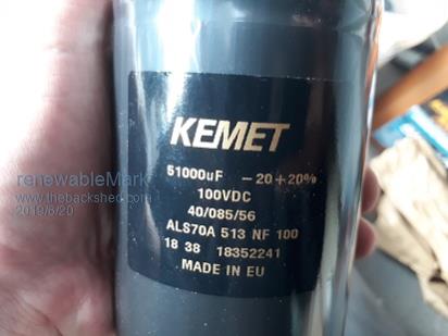 Cheers Caveman Mark Off grid eastern Melb |
||||
| Warpspeed Guru Joined: 09/08/2007 Location: AustraliaPosts: 4406 |
Here is the data sheet: https://pdf1.alldatasheet.com/datasheet-pdf/view/957108/KEMET/ALS70A513NF100.html About four of those might be a good start, with the excellent Klaus type of layout. Cheers, Tony. |
||||
| BenandAmber Guru Joined: 16/02/2019 Location: United StatesPosts: 961 |
Wow I like those caps Way too expensive for me though I'd have to save for years be warned i am good parrot but Dumber than a box of rocks |
||||
renewableMark Guru Joined: 09/12/2017 Location: AustraliaPosts: 1678 |
Warp, I didn't want to keep getting Macks thread off track so replied here. The unit really probably doesn't need to take up a heap of room. I like Macks design, but he clearly is not lacking in space. If you think about it, all we need is enough heatsink to cool for your planned power, and fans will help. Then you just have 3 extra torroids. Wonder if a vertical metal locker could be used? Plenty of area to bring in air and extract air, heavy torroids could go in the bottom to stabilise the enclosure and the fet boards up higher. The heatsinks with fet boards could be mounted to the door to allow for easy access. 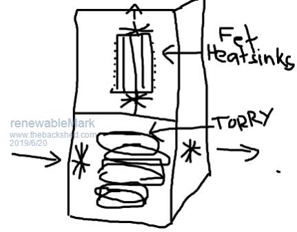 Cheers Caveman Mark Off grid eastern Melb |
||||
| Warpspeed Guru Joined: 09/08/2007 Location: AustraliaPosts: 4406 |
Yes, a vertical design like a school or gym locker should certainly work. Stack the toroids on a simple thick steel plate, fitted with large diameter heavy duty castors. Try to keep the centre of gravity right in the middle of the four castors if you can. All of the weight will then be down low, and well supported, and fairly thin metalwork should then easily support the weight of the inverter plus heat sink. The inverter will also then be at a convenient working height to allow really good access and visibility. A swing out door could also make the basis of an excellent swing out inverter. As the inverter will be generating 230v anyway, a 230v barrel type air blower to cool it might blow a lot more air with a lot less noise than a 12v computer fan, even a very big one. Cheers, Tony. |
||||
| Tinker Guru Joined: 07/11/2007 Location: AustraliaPosts: 1904 |
Good buy Mark and just a little more expensive than the ones I got. Beware, the terminal screws might be an American gauge thread (mine were) and they also were too short for 6mm bus bars. Fortunately I had some gauge screws from a junked Yankee computer that fitted. The thread looks like 5mm metric, try a M5 screw by hand, if it does not go in all the way *easily* don't force it, use the correct screw. These caps are too expensive to wreck the terminals  . .The data sheet might tell you what type screws - I did not look there. Klaus |
||||
renewableMark Guru Joined: 09/12/2017 Location: AustraliaPosts: 1678 |
Yeah, if you look down the page, it has related parts, 5mm screw is listed. Thanks for the heads up though, be nasty to stuff them up, they'll need a good connection. Cheers Caveman Mark Off grid eastern Melb |
||||
| Warpspeed Guru Joined: 09/08/2007 Location: AustraliaPosts: 4406 |
Kemet are European, so 5mm for certain. But beware, the terminal posts are aluminium and the internal threads fairly fragile. Cheers, Tony. |
||||
| Page 1 of 17 |
|||||