|

|
Forum Index : Electronics : Nano test sketch
| Author | Message | ||||
renewableMark Guru Joined: 09/12/2017 Location: AustraliaPosts: 1678 |
Hey guys, is there a sketch that will test all the functions on a nano? I searched around but could only find one for the UNO. I had an incident where a nano took the sketch ok but something must have been wrong with the actual hardware, as it didn't run the inverter. Putting in a new nano made it work just fine. So I would like to have a test sketch that operated all the components inside the little frigga and tell me if it's working OK. This would be good to test them before you start to use them. Does anyone know of such a sketch? Cheers Caveman Mark Off grid eastern Melb |
||||
| noneyabussiness Guru Joined: 31/07/2017 Location: AustraliaPosts: 513 |
The uno and nano have the same ic in them... if that helps I think it works !! |
||||
| poida Guru Joined: 02/02/2017 Location: AustraliaPosts: 1419 |
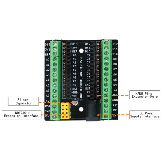
Mark, I just got one of these  from Aliexpress Maybe useful to check the function of the little beasties? I could write some simple digital output tests, you hang a CRO probe off it and observe or not the 5V pulse. Code the ADC to read each of the ADC channels, you run the serial monitor and put 5V on each channel in turn. Then check for digital inputs. Maybe all we need. wronger than a phone book full of wrong phone numbers |
||||
renewableMark Guru Joined: 09/12/2017 Location: AustraliaPosts: 1678 |
Interesting, the concern I have is potentially putting in a faulty nano onto a system with full power and caps, then BOOOOM. When testing on restricted power all this can be confirmed easily, but that's all too hard when caps are fitted. I'm getting a lot more cautious now after blowing up parts too often. Having a test power board with no caps and a known good control board is probably a better idea to test components, but ties up a bit of hardware. Cheers Caveman Mark Off grid eastern Melb |
||||
| Warpspeed Guru Joined: 09/08/2007 Location: AustraliaPosts: 4406 |
Mark, you need to build yourself a mini test inverter or a simulator, something that will verify correct driver board operation, but is difficult or impossible to blow up. Cheers, Tony. |
||||
| Tinker Guru Joined: 07/11/2007 Location: AustraliaPosts: 1904 |
Inverter #5 would be a very good candidate for this. I have a spare board set, $10 posted in Oz. Klaus |
||||
renewableMark Guru Joined: 09/12/2017 Location: AustraliaPosts: 1678 |
Yes good idea indeed, may not get to it for a while but I'll take you up on that Klaus. Cheers Cheers Caveman Mark Off grid eastern Melb |
||||
| poida Guru Joined: 02/02/2017 Location: AustraliaPosts: 1419 |
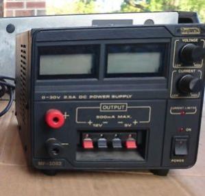
Mark, you have seen my test inverter. It doesn't look like much but it has taken some nasty stuff, gate signalling that would have blown anything else. What helps the most is not to have huge capacitors. Just fit a small amount of bulk capacitance, maybe only 3000uF. And get a proper current limiting power supply. When I recall some of the bad things I did to the test board, due to out of control PID, or just plain wrong gate drive wiring, or whatever, it's really handy to have something like the above suggestions. I always test at about 27V DC, with a small toroid wound to suit. something like this at $130 or maybe less if they take it.  It looks to be a linear supply. It's 0 - 30V, 0 - 3A would be enough. I only test dubious things with idle loads anyway and this supply can give 90W. Most idle loads I've seen are less than 20W. It's got handy 5V and 12V outputs to. It sounds like I'm trying to sell it. Sorry. Or go to Aliexpress, get a 60V, 5A switcher for about $90 shipped to AUS. Or.. wronger than a phone book full of wrong phone numbers |
||||
renewableMark Guru Joined: 09/12/2017 Location: AustraliaPosts: 1678 |
Restricted power is no problem, I just feed the 48v through two big 33 ohm resistors, that keeps the flow right down. My inverter has two breakers to turn the power on, first one feeds via two of those resistors, that charges caps up slowly, then the second one is full power, and the first one gets turned off. Very handy, I was running low on the recycled aerosharp ones, so got some of these Just need a simple power board for testing really. Cheers Caveman Mark Off grid eastern Melb |
||||