| Author |
Message |
Revlac

Guru

Joined: 31/12/2016
Location: AustraliaPosts: 1026 |
| Posted: 10:44am 28 Apr 2019 |
 Copy link to clipboard Copy link to clipboard |
 Print this post |
|
Just thought I would show this, as a bit of experience in learning how these work. Back about Mid 2016.
This was my first little inverter attempt/build, and my first practical go at electronics.
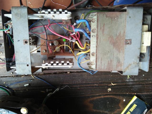
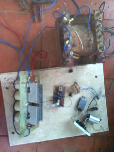
It comprised of an old Telecom 48v power supply striped out to just a transformer, then built the circuit using the little SG3524N ic and a couple of fets from an old CRT.
Runs from a 12v battery and will put out (square wave) 240vac and 50Hz either of them adjustable. (can't blow it up easily)
Has been very useful for running small stuff and testing transformers, in fact.
I used it just the other day testing the transformer for the big inverter.
I don't have a Variac so this worked out nicely.

When I found: The Back Shed forum I started a LF inverter build before I joined, to see if it was possible to build just with the information that was available at the time.
And so on it went.
EGS002 inverter build

This is just a ratsnest so I can see how everything works using an EI tranny.
The First time I fired this thing up, a big red spark flew out of the bridge... disconnected the battery power, and had a good look and could not find any damage, checked the caps and still some charge in them, so no short.
OK, powered it up again and the damn thing just works, set the voltage to 235v all good.

I have run various loads, water pump, small air con, large angle grinder, large fan and a freezer without a choke, the current draw (efficiency) was terrible.
But I must say when running with a choke the results where looking pretty good for average loads.
Had switched it on and off many times, trying different things, Had a friend was going to come over, and thought I would try it again before he arrived so he could see it working, this time I flicked the switch on and BANG, I was peppered with bits of fets. 
It was at this stage it was suggested to me by a friend from the Forum that I should invest in a CRO/oscilloscope, and so I did, best bit of advice for fault finding after blowing up the fets and drivers.
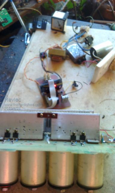
It was a good experience to prove to myself it works, and at initial cost of getting it running was about $20 worth of parts, the rest of it was just junk, the power board was just a piece of fibreglass and some copper strap, the control board was a home etch pcb. 
It was some time ago when I tested this, and haven't done anymore with it after blowing up a few fets and the 002 board.
I will revisit this at a later stage.
After watching most other builds and problems, I'm still surprised it started and worked at all, although I doubt it would have run for a long time.
Inverter builds have come a long way since I did this, and probably just as well too.
Anyway have laugh you lot. 
Anyone else have a Rough as guts build you wouldn't want to show?
just a bit of amusement.
Cheers Aaron
Off The Grid |
| |
BenandAmber
Guru

Joined: 16/02/2019
Location: United StatesPosts: 961 |
| Posted: 12:15pm 28 Apr 2019 |
 Copy link to clipboard Copy link to clipboard |
 Print this post |
|
That looks like good work to my standards wish some of my stuff looked that good and using used parts makes it that much better Edited by BenandAmber 2019-04-29
be warned i am good parrot but Dumber than a box of rocks |
| |
Chopperp

Guru

Joined: 03/01/2018
Location: AustraliaPosts: 1057 |
| Posted: 12:38pm 30 Apr 2019 |
 Copy link to clipboard Copy link to clipboard |
 Print this post |
|
Aaron,
Your exploits reminded me that I had some bits & pieces of an Electronics Australia (Dec '89) 600W PowerHouse DC-AC inverter including the big toroidal transformer up in the attic. Got it with some other junk from somewhere.
Just got it down. Has high current 10.5V secondaries plus some tertiary windings as well.
No O/P transistors or heatsinks. Does have the control board & case (no top) but other bits missing.
Must do something with it one day. Not sure what. Just gave a square-wave output.
Threw out the relevant copy of EA many years ago, but the article is available from SC for < $10. Almost tempted.
Brian
ChopperP |
| |
wiseguy

Guru

Joined: 21/06/2018
Location: AustraliaPosts: 1156 |
| Posted: 01:47pm 30 Apr 2019 |
 Copy link to clipboard Copy link to clipboard |
 Print this post |
|
Those heatsinks look like they came from an old EGA monitor ? I think I have also seen them in some older PC power supplies?Edited by wiseguy 2019-05-01
If at first you dont succeed, I suggest you avoid sky diving....
Cheers Mike |
| |
Revlac

Guru

Joined: 31/12/2016
Location: AustraliaPosts: 1026 |
| Posted: 01:07pm 01 May 2019 |
 Copy link to clipboard Copy link to clipboard |
 Print this post |
|
Brian
I think you will find a use for it, there might be a circuit diagram lurking on the net somewhere.
Have some old ETI books, I sometimes like to go back to the OLD and RELIABLE when some of the new technical things have me beat, then come back to it later when things make sense. 
This little square wave inverter mostly survives because of the loosely coupled transformer, there are other parts it should have that I did not think of at the time.
I might do another one, a bit stronger, using batteries of any voltage for the DC bus and use the IRS2453 H-Bridge, (I have some) its a bit simple and there is better option's available but it was good to learn with. Busted a few fets when turning it off, forgot to put the capacitor on the DC supply. oops. 
Cheers Aaron
Off The Grid |
| |
Revlac

Guru

Joined: 31/12/2016
Location: AustraliaPosts: 1026 |
| Posted: 01:09pm 01 May 2019 |
 Copy link to clipboard Copy link to clipboard |
 Print this post |
|
Mike. That's exactly where those heat sinks come from, I have striped down a few of those monitors and computer PSU for parts, rather than let them go for E-Waste. 
Cheers Aaron
Off The Grid |
| |

