|

|
Forum Index : Electronics : Turning on 48 v fan using 12v onboard
| Page 1 of 2 |
|||||
| Author | Message | ||||
| BenandAmber Guru Joined: 16/02/2019 Location: United StatesPosts: 961 |
Using 12v fan out put of egs002 to turn a 48 volt fan on and off A relay would be simple but can we do better with a mosfet I think poida the great uses a mosfet So what would the Circuit look like using a mosfet to turn it off and on would a mosfet use less power than a relay How about grounding when using a mosfet and wouldn't the mosfet need a diode and a resistor Sorry if this is stupid simple We are not exactly sure how we should do it We was going to buy a control module but could not find one at a decent price for the DC voltages I needed We already have 48 volt fans and would like to use onboard temp control we would appreciate all the thoughts and ideas on this subject be warned i am good parrot but Dumber than a box of rocks |
||||
Grogster Admin Group Joined: 31/12/2012 Location: New ZealandPosts: 9308 |
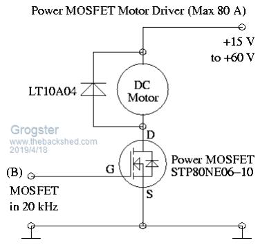
Google Images is your friend with simple driver circuits.   This image found in a few seconds when I Googled 'MOSFET motor driver'. Basically, any MOSFET with suitable S-D voltage and current to handle your fan will work. You need to be ABSOLUTELY SURE that Vgs(maximum gate-source voltage) is AT LEAST 12v(preferably a little more) in your design, or you could blow the transistor up before you get anywhere. Exceeding Vgs will usually destroy the gate and therefore, the transistor itself. In this image from Google Images, I would also like to see a 100k or so pull-down resistor between gate and source, to keep the MOSFET off in the absence of an 'ON' switching voltage. I also tend to like using a series 1k on the gate just for a bit of additional protection, but then, as there is effectively zero current flowing on the gate unlike the base of a bi-polar perhaps this is overkill. I would normally recommend my go-to MOSFET - the 14N05, but it's maximum gate voltage is 10v, so you would kill it with a 12v drive, so you will have to find another device. EDIT: The STP80NE06 MOSFET in the schematic above would work nicely. It has a Vgs of 20v, so you could drive this one happily with 12v.  Link to PDF for STP80NE06 MOSFET... Smoke makes things work. When the smoke gets out, it stops! |
||||
| BenandAmber Guru Joined: 16/02/2019 Location: United StatesPosts: 961 |
Thanks grogster I really appreciate your input I have seen many circuits like this online I just didn't know if it would cause any unexpected problems like maybe the fan continue spinning after the circuits already turned off and back feeds into the circuit or introduce noise into the circuit or hundred million other things that could happen that someone less experienced may not think of People on here are very experienced have been there done that I figured I might ask around to see if there was any unforeseen problems I might run into especially with grounding And I wanted to know if a relay would do just as good or if it would use a lot more power A lot of the questions that I asked on here I've already researched But it's real nice to have somebody that's already been there done that tell you it will be fine a lot of times they say hey this is a lot better way of doing it But thanks again for chiming in be warned i am good parrot but Dumber than a box of rocks |
||||
Grogster Admin Group Joined: 31/12/2012 Location: New ZealandPosts: 9308 |
Grounding should not be an issue when you are only driving a fan-motor, solenoid or lamp etc. The grounding becomes incredibly important with the MOSFET inverters discussed in the other threads, due to the large currents being switched. You don't really need to worry about fantastic grounding techniques when only dealing with a few amps. That is not to say it is unimportant, but GENERALLY SPEAKING, so long as your ground is present and firmly connected, you'll be fine.  With the inverters, where there can be hundreds of amps being passed, a bad ground and I-squared-R heating can blow things to bits.  Oh, and your other question "would a mosfet use less power than a relay" - yes. Most definitely. A relay 'on' current could be upwards of 150mA or more, most of which is wasted in heating of the coil, but a MOSFET gate 'on' current is microscopic by comparison. Essentially, for most applications, you can assume that the gate current is zero. Or effectively zero anyway!  Smoke makes things work. When the smoke gets out, it stops! |
||||
| BenandAmber Guru Joined: 16/02/2019 Location: United StatesPosts: 961 |
That is exactly the information I was needing thanks again I really appreciate it I will most definitely use a mosfet instead of a relay be warned i am good parrot but Dumber than a box of rocks |
||||
| BenandAmber Guru Joined: 16/02/2019 Location: United StatesPosts: 961 |
Grogster I just ordered 2 18000uf capacitors for the little China inverter board with only 4 mosfets it came with two 470 UF capacitors do you think it will die or do you think it'll be okay be warned i am good parrot but Dumber than a box of rocks |
||||
Grogster Admin Group Joined: 31/12/2012 Location: New ZealandPosts: 9308 |
I guess the only other thing to mention, is that most MOSFET's are static-sensitive - especially the gate connection, as the gap between the gate and S-D path is microscopic, and a static discharge can destroy this incredibly thin insulation between the gate itself, and the S-D path. So.....use standard anti-static procedures when handling MOSFET's. Once they are soldered into the circuit, the natural impedance of the circuit will generally protect the device - but I still use a wrist-strap just in case with pretty much any modern electronics.  Smoke makes things work. When the smoke gets out, it stops! |
||||
Grogster Admin Group Joined: 31/12/2012 Location: New ZealandPosts: 9308 |
I don't know as I don't have that inverter, but I EXPECT that if it came with 470uF caps, that it is designed to run with those OK. I know nothing about this inverter, so I am probably not the best one to advise you in that respect. Warpspeed etc are the inverter guru's here.  Can you link me to your 'little China inverter board'? Smoke makes things work. When the smoke gets out, it stops! |
||||
| BenandAmber Guru Joined: 16/02/2019 Location: United StatesPosts: 961 |
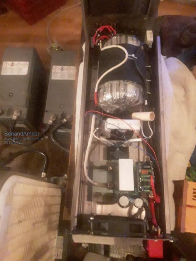
 That big case fan the one I will be turning on and off with a mosfet I am very impressed with this little board I hope by putting those giant capacitors in there it will help it even more be warned i am good parrot but Dumber than a box of rocks |
||||
| BenandAmber Guru Joined: 16/02/2019 Location: United StatesPosts: 961 |
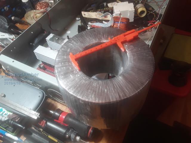
I'm sorry I don't know how to do a link on here the name of the post is little Chinese inverter board it is one of those little Chinese inverter board you can get for 27 bucks on eBay I replaceed the Mosfets it came with Hy 4008 and done all the other things that poida told me to do to it soldered in wire over the traces I've done right at 2500 watts with it with no problem and it don't complain at all For 27 bucks on eBay and a few parts good wisdom from poida not too shabby have you ever heard anyone making their own toroid core me and the wifey have done this and almost ready to wind wire on it will let everybody know how it goes  We wound the Silicon Steel around a sewer pipe and lacquered it with regular Automotive fiberglass lacquer Poor people have poor ways we'll see how it works out soon be warned i am good parrot but Dumber than a box of rocks |
||||
| poida Guru Joined: 02/02/2017 Location: AustraliaPosts: 1419 |
That's one big toroid core. The nice thing with big cores is the volt/turn ratio. One this size will be great, you won't need to wind hundreds of turns just to get to 120V. We should start a contest. Who can guess the turns needed on the secondary for 120V, without asking for dimensions. Just use the photo above. Winner get's nothing much, just admiration. wronger than a phone book full of wrong phone numbers |
||||
| BenandAmber Guru Joined: 16/02/2019 Location: United StatesPosts: 961 |
Hint on size of transformer it's really not that big it was made to fit in power jack case it's the smaller size swer pipe that we used for mobile homes but it is quite a bit bigger than the power jack I'm not 100 percent sure after we wrap it if its gonna fit in there we already have the volts per turn figured out staregazer dont get to guess because he was here when I done the math So do you guys think going to work out okay be warned i am good parrot but Dumber than a box of rocks |
||||
| staregazer Newbie Joined: 21/03/2019 Location: United StatesPosts: 1 |
The toroid is the width of a cantaloupe. Itís not as big as what the picture looks. He made it to fit in a power jack case. |
||||
| BenandAmber Guru Joined: 16/02/2019 Location: United StatesPosts: 961 |
A really big cantaloupe I have a little under an inch to wind the primary and secondary original Power Jack has lots of room vertically this one will not it will be very close that way also hope it fits Staregazer you should go read some of the post about all the different type of microcontrollers They build and program them for anyting you could imagine People on here are building and programming and sharing all that information for free If you have a cool idea thay will help you Staregazer is the friend I went in on the solar panels so he has all these solar panels half of the 107 of them that are left so he owns over 50 330 watt panels has no inverter or charge controller I have been trying to talk him into building a warp speed inverter And told him there is a mppt charge controller on here being perfected as we speak All these panels are sitting out in my yard doing absolutely nothing hopefully soon I'll have some of them up on my RV be warned i am good parrot but Dumber than a box of rocks |
||||
| LadyN Guru Joined: 26/01/2019 Location: United StatesPosts: 408 |
Wonderful recommendation! |
||||
| LadyN Guru Joined: 26/01/2019 Location: United StatesPosts: 408 |
I look forward to the thinking process! I know NOTHING about transformers so all your inputs will help me learn |
||||
| BenandAmber Guru Joined: 16/02/2019 Location: United StatesPosts: 961 |
LadyN I'm glad you chimed in This may be a way of getting a large toroid core on a tight budget This one that Amber and I made isn't all that big but it's big enough to tell if the concept is going to work or not I will keep you updated be warned i am good parrot but Dumber than a box of rocks |
||||
| tinyt Guru Joined: 12/11/2017 Location: United StatesPosts: 438 |
Using my old and tired eyes, it looks like the ID is 100 mm (3.9") and the OD is 200 mm (7.87"), roughly. Cannot guess the height. |
||||
| azhaque Senior Member Joined: 21/02/2017 Location: PakistanPosts: 117 |
BenandAmber Take a look at the spreadsheet and see if it helps. https://www.thebackshed.com/forum/forum_posts.asp?TID=11134&KW=azhaque&PN=1&TPN=1#130769 azhaque |
||||
| BenandAmber Guru Joined: 16/02/2019 Location: United StatesPosts: 961 |
Azhaque that is an absolute must read for anyone who wants to build their own core that is where I got my ideal from I read it a long time ago and could not figure out where I read it from so everything I've done was off memory but it was pretty close I highly highly recommend anyone thinking of doing this to read the article thoroughly Thank you so much for bringing up that link I really appreciate it be warned i am good parrot but Dumber than a box of rocks |
||||
| Page 1 of 2 |
|||||