
|

|
Forum Index : Electronics : Inverter #5
| Page 1 of 3 |
|||||
| Author | Message | ||||
| Tinker Guru Joined: 07/11/2007 Location: AustraliaPosts: 1904 |
Some forumites may remember this Inverter #4 which I built last year. It is great for testing purposes but I also wanted to have a go at that inverter synchronizing thing. For that task one requires two inverters and as I did not want to tie up those inverters that run my house & shed, inverter #5 was built. This is a tiny version, just 4 x HY4008's on a common heat sink. The two PCB's are the cheap 100 x 100mm size, 1oz boards. The control board uses a single nano with poida's code and only the essential functions beside the sync feature, to be able to fit on that size board. The control board was designed to eventually replace the EG8010 based control boards that are in my other inverters, so it has provision for the connectors to suit that. But I think the little inverter described below would make a very neat bench top inverter, powerful enough to run 500W all day long (limited by the PCB tracks) and yet compact enough to park on a shelf in between uses. There are some spare PCB's BTW. The power board looks like this: 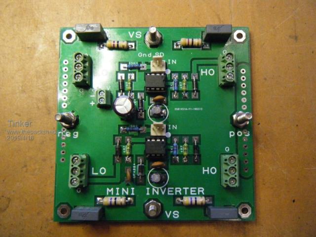 With a reverse side like that: 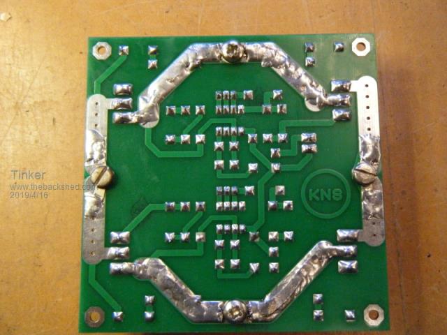 Note how I beefed up some tracks (the ones to the primary) with solder wick. The positive & negative power tracks are duplicated on both PCB sides for that purpose. To avoid current hot spots I also soldered solder lugs to beef up the track, you may just be able to spot them under the screw heads. Here is that board fitted to a single heat sink - doing that requires insulating washers *must* be used under the mosfets:  The control board looks like this; 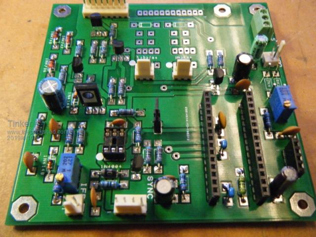 This board can also accommodate the half bridge drivers, these will be fitted on my big inverter replacement boards as these inverters use totem pole drivers on the power board as well. There was no room for the LT1638 filter on that board so I can fit this as a 4 way plug in little daughter board (next to the nano). The nano seems to run well without that board (still waiting for that PCB), perhaps that has to do me using a ground plane? The control board piggy backs on 25mm spacers, see picture further down. Now, in my experience, bench testing something that has many individual parts, like an inverter, requires a rats nest of wires an this resulting often in dubious connections. To avoid that, time spent to make a little plywood caddy, to fit all the parts, is well worth while. This is what I came up with: 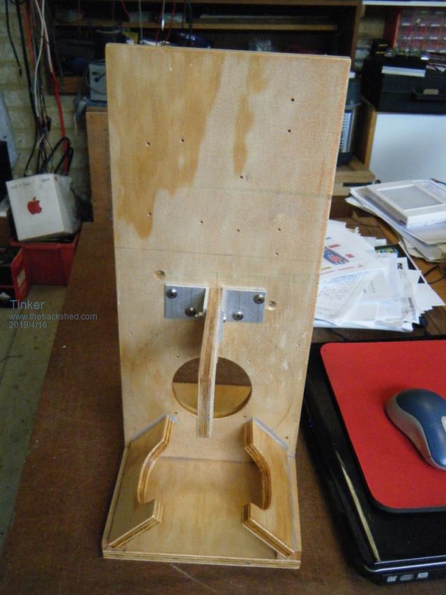 And here are the parts fitted to one side: 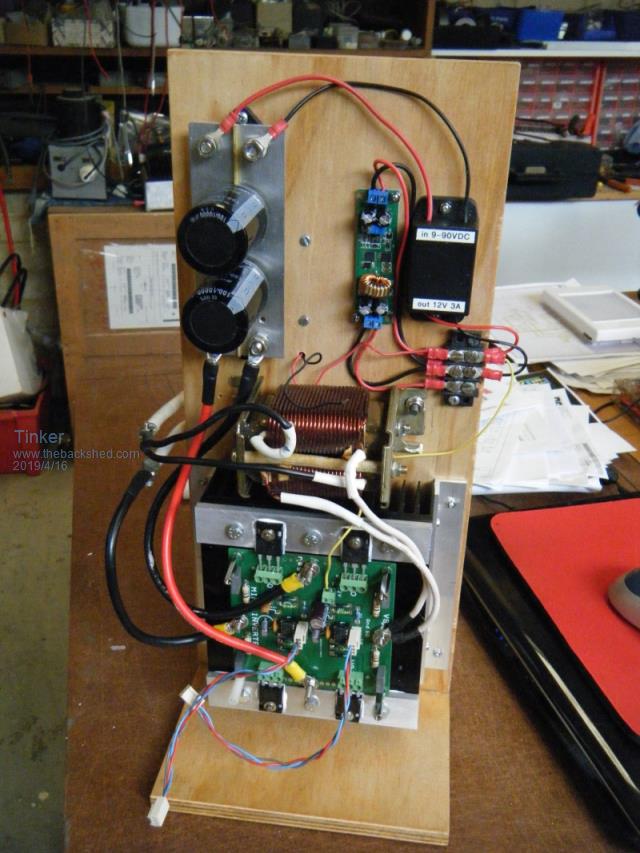 And the other side: 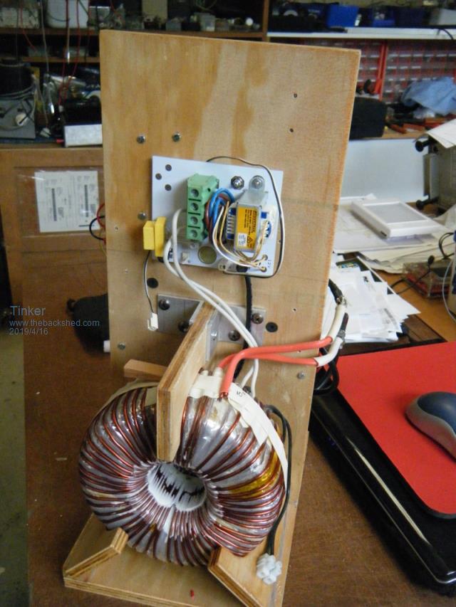 All being connected up, time came to apply power and see what happens. I used a small pilot light for a load as the inverter was powered by my bench power supply then: 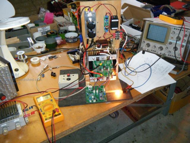 Well, it worked  , with a beautiful soft start and stop. Nice clean sine wave too. , with a beautiful soft start and stop. Nice clean sine wave too.Further testing with a 60W, then a 100W incandescent light - still running fine. 200W lamp, still fine but not for long as the 10A fuse in my power boost module complained about too much load  . .Here are some close up shots of the two PCB's connected up: 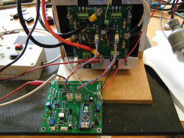 Note the plug in gate drive connectors so the control board can be easily removed. A close up of the control board fitted piggy back to the power board: 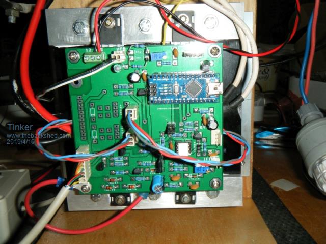 And here is the full power test set up, #4 inverter is located on the left and #5 inverter on the right: 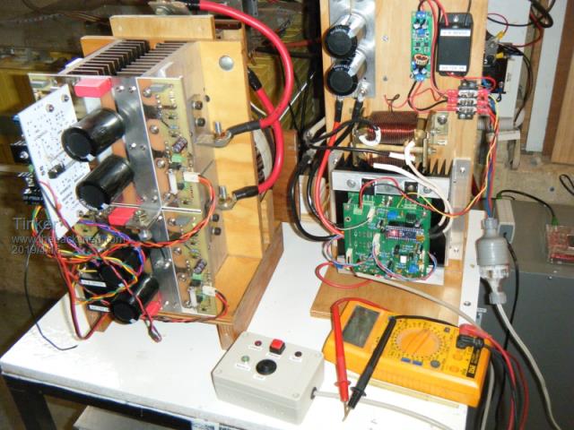 There is a 80mm 12v fan behind the heat sink (switch controlled) but with a 500W load it was not required to run, the heat sink (and top of mosfets) were only 10 degrees above shed ambience temperature. The choke got warmest, I used a small one from a 2500VA Aerosharp with both coils in parallel. I might experiment with different chokes here later. The toroid, recycled out of a 1KW, 96V Latronics inverter, uses the original secondary. This got warm to touch after running 500W for several hours. The sine waves are interesting, here it is with a 500W load:  I use a light bar with flood lights as test load, this lets me increment it in 100w steps. 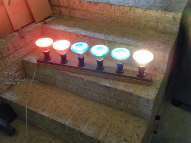 This is how the sine wave looks with 600W: 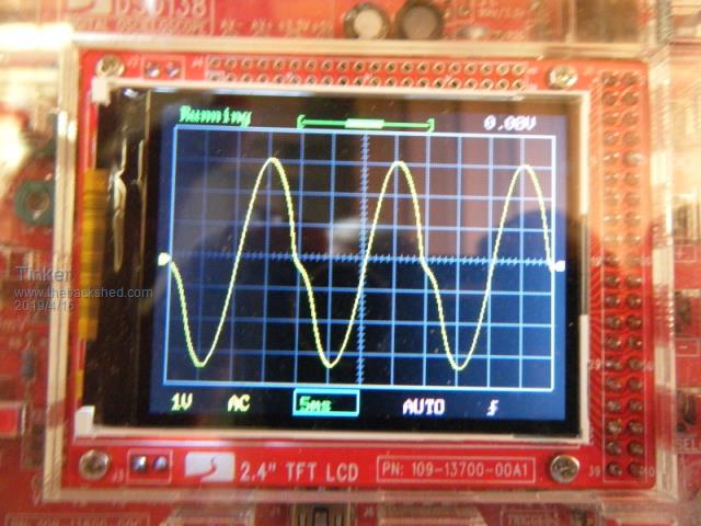 I have no idea what causes the down slope distortion yet, more experimenting with chokes perhaps required. No distortion up to 500W load, then it looks like something is working too hard. Its not the Mosfets, with inverter #4, a 4 Mosfet bridge was tested to well over 1KW before they overheated and quit. Next on the list is to build a little relay box to facilitate the sync function between those two inverters. Inverter #4 with the EG8010 chip will be the master, the nano inverter the slave. I am particularly interested how these two share a common load, I shall have #4 with just 4 HY4008's initially as well. That can be increased to 12 CMos later. Klaus |
||||
| poida Guru Joined: 02/02/2017 Location: AustraliaPosts: 1419 |
I watch the progress of this with much interest. The distorted waveform at 600W has me puzzled. There is a hint of it at 500W in the above image. I suspect the toriod might have suffered a big whack at some time, and is magnetised as a result. But also, you might want to verify correct DC supply to all 4 legs of the bridge. At zero AC voltage crossing, we have max AC current. I am thinking you might see the kink on the upward slope, from negative AC voltage past zero to max +peak. Just change the two primary wires around and the scope's sample wires, to retain the same "sense". That way, you only change the current direction? Are you able to show the primary current on the scope too? wronger than a phone book full of wrong phone numbers |
||||
| Tinker Guru Joined: 07/11/2007 Location: AustraliaPosts: 1904 |
I'll try swapping the primary wires tomorrow. The sinewave was probed across the capacitor at the secondary - easiest to attach probes at. If you look at the PCB tracks of the power board, there is nil chance for unequal DC to the bridge (assuming you mean the Mosfet power source & drain legs?) No, I do not possess a current probe for my scope. She's a 30 year old BWD dual trace/ 35MHZ old fashione CRO job with no fancy probes. I took the pictures on the cheap little digital scopes as on these the full trace gets captured by my camera. There is an identical trace shown on the dual channel analog CRO but very hard too photograph with hand held camera. What I can reasonably easily do is assemble another nano control board and fit it to inverter #4. That should give me a good comparison as there is a bigger toroid and decent choke on that. Klaus |
||||
Revlac Guru Joined: 31/12/2016 Location: AustraliaPosts: 1026 |
Looks nice and neat. Tinker I'm starting to like the Idea of using the 100mm boards, where possible. will keep watching your progress.  Cheers Aaron Off The Grid |
||||
| tinyt Guru Joined: 12/11/2017 Location: United StatesPosts: 438 |
Tinker, Very nice. I think I remember seeing that kind of kinky waveform when I was experimenting here |
||||
| Ralph2k6 Senior Member Joined: 24/09/2017 Location: AustraliaPosts: 129 |
Wow, some beautiful craftsmanship yet again Tinker.  That arrangement could serve very well for offgrid supply to small circuits such as house lighting, or perhaps 'portable mains' power. I expect an obvious answer but, have the 4 mosfets been Rds matched using the load test method? (10 amps, check mV drop etc etc). Will be lurking/watching with great interest. Ralph |
||||
| Tinker Guru Joined: 07/11/2007 Location: AustraliaPosts: 1904 |
Yes Ralph, I do load test my Mosfets to match them. But there were not very many left in my stock so I selected them (from memory) to be within 0.2 mOhm. I have some more on order and will swap them later, easy to do with terminal connections  . .I tried poida's suggestion of swapping the primary connections over, the distortion moved to the upslope then. I think it has to do with the choke as other chokes I had here all produced (different looking) distortion above 500W or so load. The plan now is to make a decent non saturating choke for that little inverter. Also, to assemble another control board so the nano can be tested in the bigger inverter #4. I found the AC voltage regulation was not very good at inverter #5. Increasing the load from 300W to 600W dropped the AC voltage from 230 to 225V. As I found out when testing inverter #4, just four HY4008 Mosfets could handle in excess of 2KW on a big heat sink. That little power PCB of inverter #5 has current limits but I'm keen to find out if I can push it up to 1KW without blowing PCB tracks. At that power it would indeed become quite useful for some applications. There is no end of experimenting fun to be had by having several inverters  . .Klaus |
||||
| wiseguy Guru Joined: 21/06/2018 Location: AustraliaPosts: 1156 |
Let me reword this, if you have current sensing employed try removing it briefly & then try out the 600W test - which should be quite safe to do and see if it improves the waveform shape ? If you are using a current sense transformer with only a single diode for rectification it could cause distortion that only affects one half of the waveform symmetry. Is this a mistake - I am having trouble understanding what this means, if there is no AC voltage (zero cross) then for a resistive load, AC current should be zero too ? If at first you dont succeed, I suggest you avoid sky diving.... Cheers Mike |
||||
| Tinker Guru Joined: 07/11/2007 Location: AustraliaPosts: 1904 |
Thanks for your input Mike and no, there is no current sensing at all employed at the moment. There is a little transformer used for voltage feedback only. Klaus |
||||
| wiseguy Guru Joined: 21/06/2018 Location: AustraliaPosts: 1156 |
I really like the Poida nano1 control system. I have been using it for bench testing and evaluation of a 12 - 235V Inverter at 250W nominal and it works a treat. I am awaiting the arrival of some 48V batteries for a bit more serious fun. I have had more luck with the earlier code that had the Bessel filter functions in - I will take this up with Poida in due course when I have more data and information to support what I have found, there is something happening that I dont fully understand.. I have not noticed any distortion on my system but I am using a sample and hold rectifier that holds the peak value for the nano to read each half cycle. I am also using the small 2mA/2mA transformer for my feedback. The fact your distortion occurs at higher power levels implies to me that it is not related to drive symmetry per se but that something is affecting the voltage feedback at the higher power level ie ground loop, extra noise pick up, transformer interaction between the small voltage transformer and the toroid or similar issue and it is affecting the symmetry of the voltage feedback signal which then affects the symmetry of the drive waveform. Just keep on tinkering  I am confident you will nail it in time - every thing happens for a reason but it isnt always easy to find the reason..... I am confident you will nail it in time - every thing happens for a reason but it isnt always easy to find the reason.....I like your simple controller and Power PCBs - I love the 100mm x 100mm dirt cheap PCB's format & also exploit them regularly. I also forgot I could take advantage of the extra space under the nano control board unlike yours! If at first you dont succeed, I suggest you avoid sky diving.... Cheers Mike |
||||
| Tinker Guru Joined: 07/11/2007 Location: AustraliaPosts: 1904 |
Very useful info, as usual, from you Mike. I certainly will investigate that possible VFB interference. I try hard to avoid ground loops and the boards have a ground plane too. But there is no VFB filter LT1638 installed as yet, the little daughter PCB for it has not arrived, due any day now. Will also try shielded wire for the VFB link, its about 30cm long. I'll try turning that little transformer 90 degrees & see if there is a difference. Usually toroids do not have much of a stray magnetic field? 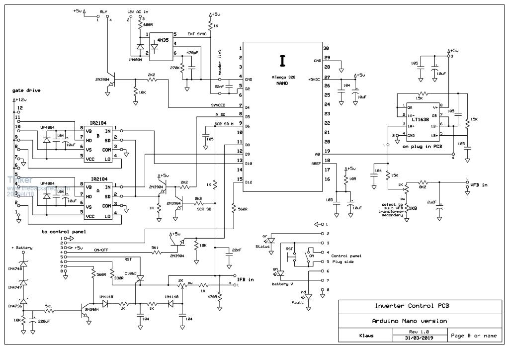 Klaus |
||||
| wiseguy Guru Joined: 21/06/2018 Location: AustraliaPosts: 1156 |
The version I have been using for best results is nano_1_v3_sync_pid. If you are using Poidas latest code V7? that has the Bessel function off, I suspect it was created using the active filters, you might be better off trying the V3 code to see if it behaves better without using the active filters in Voltage F/B circuit (which you arent using?). 2019-04-18_005703_2019-02-10_230241_Archive.zip (use Nano1 code....) If at first you dont succeed, I suggest you avoid sky diving.... Cheers Mike |
||||
mackoffgrid Guru Joined: 13/03/2017 Location: AustraliaPosts: 460 |
Klaus I always enjoy your threads. Always interesting. I've read them all, and I think I'll read them again. Keep thinking outside the box. +10  |
||||
| ltopower Regular Member Joined: 08/03/2019 Location: United KingdomPosts: 64 |
What was the primary choke you were using (uH / turns) ? The test swapping the primary certainly did make it look like the choke is the culprit.... The choke value does have a sweet spot from testing I did... idle amps vs turns on an E70.. 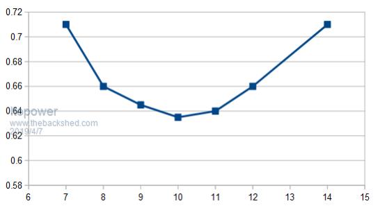 |
||||
| poida Guru Joined: 02/02/2017 Location: AustraliaPosts: 1419 |
I confirm that v3 has the digital Low Pass filter enabled and it expects a very moderately filtered Vfb signal, and probably works fine with none at all. It also works OK with the op-amp LP filtered Vfb signal. v7 has zero digital filtering on Vfb. This means we need to provide a filtered Vfb signal at the pin. The op-amp derived LP filter performs very well in this application, when fed something in accordance with TinyT's schematic. Benefits of v7 are a faster response to transients. wronger than a phone book full of wrong phone numbers |
||||
| poida Guru Joined: 02/02/2017 Location: AustraliaPosts: 1419 |
When all my inverters are running with zero load (idle), I always see the primary current to be 90deg phase different with AC voltage. This is typical: (light blue is primary current, dark blue is AC volts) 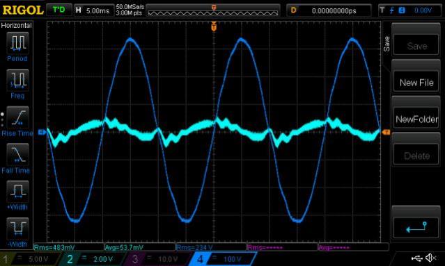 It includes some of the PWM induced wobbles, but that is not important to the point I make. It peaks around the zero crossings. The non-zero current, when under zero load is due to the magnetising of the toriod core. It's typical of an AC circuit with an inductive load. Not all of the power is returned by the toriod when it flows back to the inverter board. Some is lost. Typical idle primary winding AC current I find to be 6 A RMS The DC current is only 0.4A, at 27V. 11 W idle power. But the AC clamp meter shows 6 Amps? At 50 times a second, the inverter board is magnetising the toriod core nearly 100% in one way, then to nearly 100% the other way. There will be some loss in this activity. My interest lies in the question: What if the toroid core has some degree of permanent magnetism, in one direction only of course. What would we see? Once we add a load, there will be current varying or following the AC volts, depending on power factor. Incandescent lights are practically 1.0 power factor. These loads will have primary current varying very closely with AC load power. This is where I am in error, when I stated current peaks at AC volts zero crossing. The 600W oscilloscope trace is clearly under load of the lights, and not idle. I done a wrong. Whoops. ** when I use "magnetising the core", it is not good enough. There are more accurate ways to describe it, using the correct terminology and concepts. wronger than a phone book full of wrong phone numbers |
||||
| Tinker Guru Joined: 07/11/2007 Location: AustraliaPosts: 1904 |
If you are using Poidas latest code V7? that has the Bessel function off, I suspect it was created using the active filters, you might be better off trying the V3 code to see if it behaves better without using the active filters in Voltage F/B circuit (which you arent using?). That little PCB for the LT1638 filter arrived today and I fitted it to my nano control board. The inverter now powered 600W without distortion on the sine wave. I replaced the VFB wires with a shielded cable too. Then I was wondering if that inverter can do more power and plugged in (inverter powering 600W then) another 150W floodlight. That caused a 'bang' event  . One of the HY4008's short and one O/C. Also the top of one IR2184 half bridge driver blown off. . One of the HY4008's short and one O/C. Also the top of one IR2184 half bridge driver blown off.It got too late to investigate why that happened, will do that tomorrow. Fortunately no Mosfet leg fire happened, no visible damage to them at all. The terminals make it easy to swap for good ones. Never a dull moment with these inverters  . . Klaus |
||||
| wiseguy Guru Joined: 21/06/2018 Location: AustraliaPosts: 1156 |
Klaus, glad to hear that the active filter fixed your distortion - I was not confident about it being choke or toroid related & it seemed to me like a Voltage feedback issue from the symptoms. When you plug in/turn on a 150W lamp their surge current draw for a few cycles is considerably more than their normal running current. On top of that is, where in the mains cycle was it when the lamp circuit was coupled to the feed, if it was at its peak Voltage I'll get you to do a sum for me. Measure the resistance of the lamp filament (when cold) with an ohm meter, if the mains was 235V (332V peak) multiply 332 x 332 and divide it by the cold resistance to see what the instantaneous power requirement was (might have been?). It may help to explain why your FET's weren't happy? (E x E /R = watts) I wouldnt be surprised if it was between 1 & 2 kW on top of the 600W. If you had powered down, then added the lamp and allowed the soft start to do its thing it might still have worked - of course its also very boring by comparison..... If at first you dont succeed, I suggest you avoid sky diving.... Cheers Mike |
||||
| Tinker Guru Joined: 07/11/2007 Location: AustraliaPosts: 1904 |
I see you are a bit of a night owl Mike, and as wise too  . I came to the same conclusion after thinking about that for a while. That last floodlight was a halogen type with the glass tube element. . I came to the same conclusion after thinking about that for a while. That last floodlight was a halogen type with the glass tube element.I'll see if I can get that inverter soft start 1KW and still have minimal distortion. That toroid is not rated for more power, IMO. Am also soldering parts to another nano control board for my inverter #4 so I can compare its performance with totem pole final drivers. Klaus |
||||
| Tinker Guru Joined: 07/11/2007 Location: AustraliaPosts: 1904 |
Its going again, had it power a 1KW load, no problem. That 'bang' event also took out the little DC/DC converter, used to get 12v from the battery, my nose eventually told me just where the no low voltage problem was  . .Here is a picture of the sine wave with a 1KW load (500W immersion heater + 5x100W floodlights): 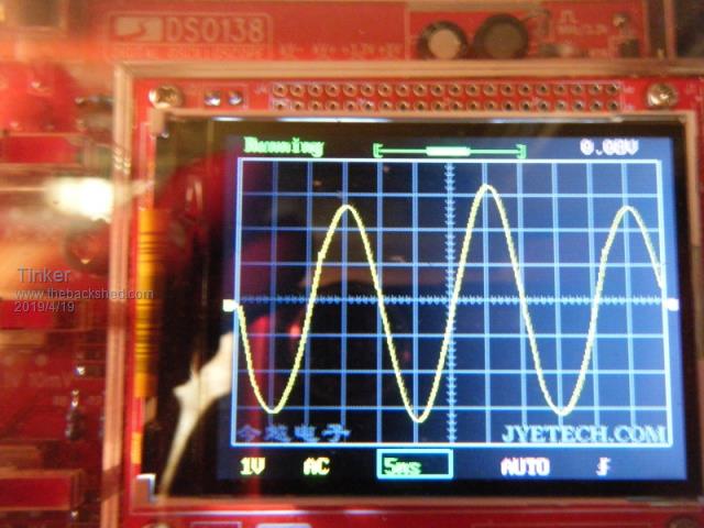 One thing odd about that was every other peak was bigger and that alternated top & bottom peak, sort of moving along the wave train. So I looked at it with my analog CRO, no such odd peaks but HF noise at the wave peaks instead. It looks as if that little digital scope does some kind of averaging, producing that odd sine wave. The noise is because I used one of the ferrite chokes (E65 core, 4.5 turns) that I took out of my ozinverters for testing. I'm now making a non saturating choke using the C cores from the Aerosharp, those chokes made a big improvement in my ozinverters compared to the ferrite job. Here is a picture of the plug in R/C loads to see the nano output waves. These make testing that very easy. 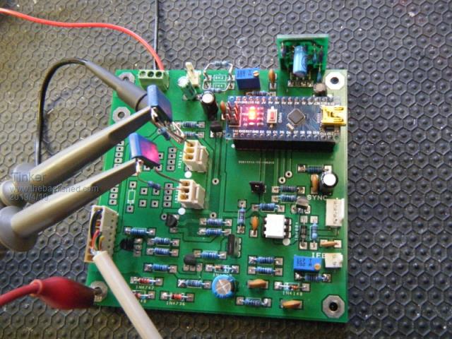 That little active filter board can be seen at top right, behind the nano, of the PCB. Klaus |
||||
| Page 1 of 3 |
|||||