
|

|
Forum Index : Electronics : Excel Sheet for Transfo Design
| Page 1 of 2 |
|||||
| Author | Message | ||||
| azhaque Senior Member Joined: 21/02/2017 Location: PakistanPosts: 117 |
Hi all, An excel sheet for designing E-I or Toroidal Transformers is attached. Comments pls. Regards 2019-02-12_214236_transformers2.zip |
||||
mackoffgrid Guru Joined: 13/03/2017 Location: AustraliaPosts: 460 |
Hi azhaque, Good stuff. I am more familiar with the Toroid calculations (not expert) so I'll comment on that. In A4 you describe width of sheet, you might want to show it as height as well. You input flux density which is fair enough but you may want the reverse calculation, say you have a transformer and you want to calc the flux density from the volts/turn (and core cross area). It may also be helpful to show volts/turn. Are you going to build your own core? Cheers Andrew |
||||
| johnmc Senior Member Joined: 21/01/2011 Location: AustraliaPosts: 282 |
Good Day azhaque Thanks for the spread sheet on transformers design. The proposed toriodal core appears to be to small on the internal diameter, as a it will be difficult to fit all the conductors required, for a 6kw transformer, maybe increase the dimensions to have a internal diameter to 100 mm . cheers john johnmc |
||||
| azhaque Senior Member Joined: 21/02/2017 Location: PakistanPosts: 117 |
Hi Andrew. Hi John. Andrew. I have changed the nomenclature to Width/Height in A4 to make it commensurate with the diagram. The suggestion you make about reverse calculation is also useful. However the problem that I see is regarding actual core dimensions. As I see it, core material is covered with various materials (sometimes epoxy) before the first layer is wound. Therefore even if you were able to unwind the transformer, the actual core dimensions would be un measurable as these protective layers may or may not be removable. Maybe someone can put me wiser on this point. Yes I do plan to wind my own toroidal transformer. I have just made an 5KW inverter based on a Chinese inverter board that uses the EG8010 chip (will post pics). The transfo used therein is an E-I based unit. No load loss measured with a power analyser showed 80 Watts. Since I live off-grid this no-load loss is un acceptable. So I am planning a toroidal transformer now which should bring down the no load losses to around 20-30 watts. Toroidal cores of various sizes and voltages are not available in Pakistan and importing one from China makes the cost prohibitive. So, I am constrained to make one. Hence this Excel sheet. I attach a revised version in which I have brought in the concept of Effective Cross Sectional Area. This is to account for the air gap that maybe left between the layers of the spirally wound core. This is because in a homebrew core the winding of the core is not likely to be so tightly done so that there are no air gaps left between adjacent layers. This would reduce the area thru which the flux can flow. John. Thanks for the advice. Yes I did factor it in thinking that the inner most turns are not like to be wound with a small radius as well as the fact that thick wires (good for 150 amps or so) have to be threaded in that hole. Having a model on a spreadsheet gives me the flexibility to incorporate the new number and see what the theoretical outcome would be. Please help if you can, to validate the Excel sheet with some live known core data, if you have some. Thank you and regards azhaque2019-02-13_165307_transformers4.zip |
||||
| Clockmanfr Guru Joined: 23/10/2015 Location: FrancePosts: 429 |
There are many things interacting on the toroid to get the idle power down to 30/40 watts. Primarily the Choke is very important. Here is my new roughed out Chapter 4 of the Toroid build, in 4 parts PDF, with some genuine empirical evidence. 2019-02-13_191451_Chpter4a.pdf 2019-02-13_191531_Chapter4b.pdf 2019-02-13_193908_Chapter4c.pdf 2019-02-13_193934_Chapter4d.pdf Everything is possible, just give me time. 3 HughP's 3.7m Wind T's (14 years). 5kW PV on 3 Trackers, (10 yrs). 21kW PV AC coupled SH GTI's. OzInverter created Grid. 1300ah 48v. |
||||
| Warpspeed Guru Joined: 09/08/2007 Location: AustraliaPosts: 4406 |
There is a curious mathematical property of circles that may come in handy knowing, when planning how many turns per layer will fit on each layer, particularly for a multilayered secondary. As you add layers, the hole size obviously becomes smaller, and each additional layer has to fit into a rapidly shrinking circumference. If everything is perfect, each additional layer will have room for exactly six less turns than the layer directly underneath. If planning to wind on four secondary layers, the fourth inner layer will only have room for 24 turns less than the first layer. Amazingly this odd effect is independent of both toroid hole size or wire diameter. Here is a fairly dramatic picture to illustrate this with huge wire. If nine turns will fit onto the first layer, six less turns than that are all that is going to fit onto a second layer. 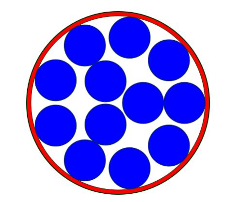 With very fine wire. if 180 turns would just fit onto a first layer, expect to have room for only 174 turns on the second layer, and 168 turns on a third layer, and so on. Prove it yourself with a bag of small washers arranged around inside the rim of something like a large paint can. Cheers, Tony. |
||||
mackoffgrid Guru Joined: 13/03/2017 Location: AustraliaPosts: 460 |
Hi Azhaque, Im working my way through your SS. I've never allowed for air gap between the steel layers (toroid). Is 0.1mm normal? sounds large to me but I wounldn't know. If so, it really knocks some of my calculations around. In cell "I8" you have =(I14+I14)/2000*I20 should that be =(I14+I16)/2000*I20 ? Cheers Andrew |
||||
mackoffgrid Guru Joined: 13/03/2017 Location: AustraliaPosts: 460 |
Azhaque, the weight of your core seems far out, I had ~35kg and your calc of 14kg is too far out. I made the change in "I8" and that brought it to 35.1kg, the same as mine. Cheers Andrew |
||||
mackoffgrid Guru Joined: 13/03/2017 Location: AustraliaPosts: 460 |
Azhaque, I think yu have a problem with your turns/volt. I work it out the other way, volts/turn but that doesn't matter. at "I4" you have =(10000)/(4.44*B50*B52*(I4*0.01)) where I4 is the cross-section-area. Did you intend on using the "Effective cross-ection-area" ? If not, what is the point of that cell "I6" ? Otherwise, my volts/turn works out the same as your turns/volt if I inverse it  . .Cheers Andrew |
||||
| azhaque Senior Member Joined: 21/02/2017 Location: PakistanPosts: 117 |
Clockman, I am personally indebted for the above pdfs. Please accept my thanks for the same as well as on behalf of the members of the forum for which these would certainly be very helpful in their future adventures with toroids. Thankyou again and Regards |
||||
| azhaque Senior Member Joined: 21/02/2017 Location: PakistanPosts: 117 |
Andrew. Good morning. http://www.posco.com/homepage/docs/eng5/dn/company/product/e_electrical_pdf_2011.pdf The above is the POSCO datasheet for their electrical sheet. If you look at the tables, the last column is titled "Lamination Factor". In the data sheet this varies from about 95-98%. I have taken this to be about 66% in the transfo excel sheet. As I submitted earlier the 95%+ Lamination Factors are likely to be possible only when the core is being pressed using hydraulic presses and all kinds of industrial machines, designed for this purpose. In the backshed manufacturing process this would not be possible. Secondly the silicon sheet used in large transformers is around 1-1.5 meters wide. This sheet is slitted on machines to specific width leaving 'scrap' sheet that backshedders like us lay their hands upon and make our own transfos. At least this is what happens here in Pakistan. The secondary market for small transformers of the 100 Watts range uses E-I cores carved out of these scrap sheets. The slitted sheet you are likely to get is likely to have burrs and un-eveness, particularly at the edges due to the slitting process. Note that Clockman's pdfs talk about sanding the edges. I can divine the purpose of this process is to remove the burrs etc. that I have mentioned above. Now you maybe right that perhaps 66% maybe a bit too high. But I figured that 0.1 mm is about as thick as the human hair. So for an amateur build I wouldn't hesitate to err on the conservative side. The consequences otherwise are smoking MOSFETS if the core saturates. So take your pick  Am travelling to Lahore today. Should be back in a day or two. Will discuss the rest of the posts then. Meanwhile may I request that the changes you suggest may kindly, if convenient, be accompanied by the equation that I can put in the cell to test the sheet for errors or adjustments. Thanks everyone for participating and your thoughtful input. Regards azhaque |
||||
| azhaque Senior Member Joined: 21/02/2017 Location: PakistanPosts: 117 |
Thanks Andrew, I amended my sheet as you suggested and it also showing 35 kgs. Thanks azhaque |
||||
mackoffgrid Guru Joined: 13/03/2017 Location: AustraliaPosts: 460 |
Hi Azhaque I admit to putting no thought into lamination factor in the past. Its perfectly obvious that it should have an impact. I believe you could estimate lamination factor of a transformer by measuring the weight. It explains why I have found discrepancies in weight, not by lots, maybe up to 5%. Good Stuff - it'd be great to see photos of what you transformers you build. Cheers Andrew |
||||
| azhaque Senior Member Joined: 21/02/2017 Location: PakistanPosts: 117 |
Good morning Andrew. I attach herewith the revised SS (tranfo5.zip) incorporating the changes and comments suggested in the previous posts, for the forum's review. What I have learnt from the above discussion is that a choke (in series with the transformer's input leads connected to the MOSFETS) is of primary importance in reducing no-load current (thanks Clockman for that insight). My question is therefore as follows. Since I already have the E-I transfo built, what are the design parameters of the choke that must be added in series with the E-I core to reduce the no load current. A bit of background. I have used a Chinese inverter board for designing my inverter. The design notes on the aliexpress website indicate that an E-I transformer would not need a series inductance choke. Now after construction of the inverter I have found that a choke is NECESSARY. I am now trying to read up on the theory of why a choke is necessary for reducing no-load current. Maybe ClockmanFr or Warpspeed or others can dilate this point further. Additionally what is the best and most cost effective method to build such a choke. Will it be iron-cored or ferrite or air? My engineering sense tells me that Iron is out because at 150KHz or so, Iron would probably be useless. The one that is being marketed by the Chinese inverterboard maker is ferrite and its inductance is 47uH. How is this value calculated, is not mentioned on the page. I ask these questions because I would like to add a spreadsheet for the choke design, into the transformer design excel spreadsheet. This would make the SS much more wholesome and useful for the backsheders like us. Regards azhaque 2019-02-16_134003_transfo5.zip |
||||
| Warpspeed Guru Joined: 09/08/2007 Location: AustraliaPosts: 4406 |
O/k let's look at our large efficient inverter output transformer (toroid or E core) that probably has a step up turns ratio of about 8:1 (30v to 240v). Its a wonderful thing at 50Hz, and if there are enough turns to keep the flux density low, the magnetizing current should remain nice and low (when driven by a 50Hz sine wave). Now what happens if we connect this DIRECT to a very low impedance PWM switching bridge switching at 23 Khz? The secondary of our transformer will have a lot of capacitance between turns, between layers, and between the secondary and the core. The secondary inductance will be very high, but there will be a self resonance of only a very few Khz with all that self capacitance. The combined capacitance across the secondary is reflected back into the primary at a rate of turns ratio squared. So there will be x64 the secondary capacitance that the bridge sees as a direct load. That capacitance has to be charged and discharged 23,000 times per second. If the transformer connects directly to the bridge there are going to be some pretty fearsome current spikes every PWM switching cycle, even with no external load on the transformer. This will definitely increase idling current, but worse, its going to really stress the mosfets as the current spikes will be almost unlimited with such a low source and load impedances. So we fit a series choke into the primary to vastly reduce the rate of current rise each time the bridge switches. With sufficient inductance the voltage at the bridge can switch very fast while the voltage across the transformer and its capacitance hardly changes. You will see a very fast high frequency rail to rail waveform on one end of the choke, and a smooth 50Hz sine wave on the other end of the choke with only a very slight high frequency ripple feeding the transformer. Now in the early days of all this inverter development, it was discovered that a ferrite choke would greatly reduce the idling current, and it will certainly do that. The problem with ferrite is that it saturates very easily, and although it will reduce idling power, above a few amps through the choke and primary, it will saturate and have no effect at higher power. We really need a choke that will keep on working up to full rated inverter power and ideally beyond, to greatly reduce the switching losses in the mosfet bridge. This will create far lower switching current spikes, reduce the stresses and heating on the mosfets and heatsinks, and generally improve inverter robusness and efficiency. How big ? Well minimum might be something like 50uH would certainly work at 48v and 2-3Kw but something a fair bit larger would be better if you can arrange it. It really cannot be made too big, either in inductance or saturation current. Its rather like the decoupling electrolytics. More is always better. When you have a really nice big non saturating high inductance choke working, it will effectively decouple the transformer from the bridge, and it allows the transformer to "do its own thing" as far as any self resonant behavior goes. Expect to see some wobbles develop in the 50Hz waveform due to transformer self resonance, especially at zero load. With higher loading the wobbles usually become slightly less. The wobbles are not caused by the choke, but actually indicate that the choke is working properly. Some people get alarmed by the now distorted sine wave output, and assume fitting a much large choke is the wrong thing to do. Fixing one problem has just created another problem, but its definitely a BIG step forward fitting a large non saturating steel cored choke. One sneaky solution to the waveform distortion is to lower the self resonant frequency of the transformer down to exactly x1.5 times the inverter frequency. That is 75Hz transformer resonance for a 50Hz inverter, and that usually takes around 4uF to 10uF across the secondary, but that varies a lot from transformer to transformer. This also sounds a bit suspect.... But try it and see, it definitely works ! The magic of exactly x1.5 times the inverter operating frequency produces a self damping effect, where any resonant buildup on one cycle will be exactly out of phase the following cycle. If its not tuned exactly right, resonant energy can build up causing even worse waveform distortion, and the inverter output voltage may do some very strange things at zero load. Voltage feedback may lose control. But if you get the transformer tuning exactly right (ideally +/- 1Hz) after fitting a really nice large non saturating steel cored choke into the primary, a great many problems will have been solved, and you will then have a sweet running and efficient inverter with a good clean low distortion sine wave at the output. Cheers, Tony. |
||||
| Clockmanfr Guru Joined: 23/10/2015 Location: FrancePosts: 429 |
Yet again 'Warpspeed' a beautiful explanation for the Choke. My hat is 'duly raised'. azhaque, As you are starting to see, their are many variables at play here with making a Inverter that has a toroid transformer. Personally I like to keep things as simple as possible, and use minimum materials. Regards the actual toroid's themselves, as I have already mentioned, 'Oztules' came up with a empirical evidence formula for each toroid, (especially as he was using stacked used/second hand rewound cores), that would give a general calculation figure for each bare toroid core. Then using my previous mentioned electrical test procedures we can insure we are getting each core to behave in the required area. Everything is possible, just give me time. 3 HughP's 3.7m Wind T's (14 years). 5kW PV on 3 Trackers, (10 yrs). 21kW PV AC coupled SH GTI's. OzInverter created Grid. 1300ah 48v. |
||||
| johnmc Senior Member Joined: 21/01/2011 Location: AustraliaPosts: 282 |
Good Day Warpspeed Thanks again for your input, on the magic world of transformers. cheers john johnmc |
||||
| azhaque Senior Member Joined: 21/02/2017 Location: PakistanPosts: 117 |
Gentlemen, There is enuff in the above posts to take a few hours to digest. Thanks Warpspeed, Clockman et. all. Will continue on the technical aspects later. So this session for uploading video and photos only. Youtube video of first electrons of homebrewed inverter . The top platform with the inverter board and instrumentation. 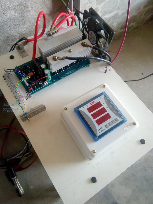 The transformer under the top platform. 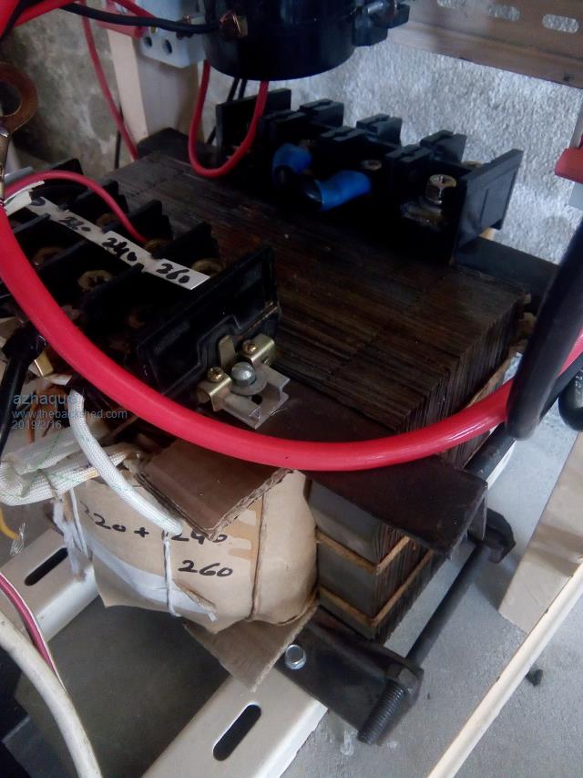 The Chinese inverter board 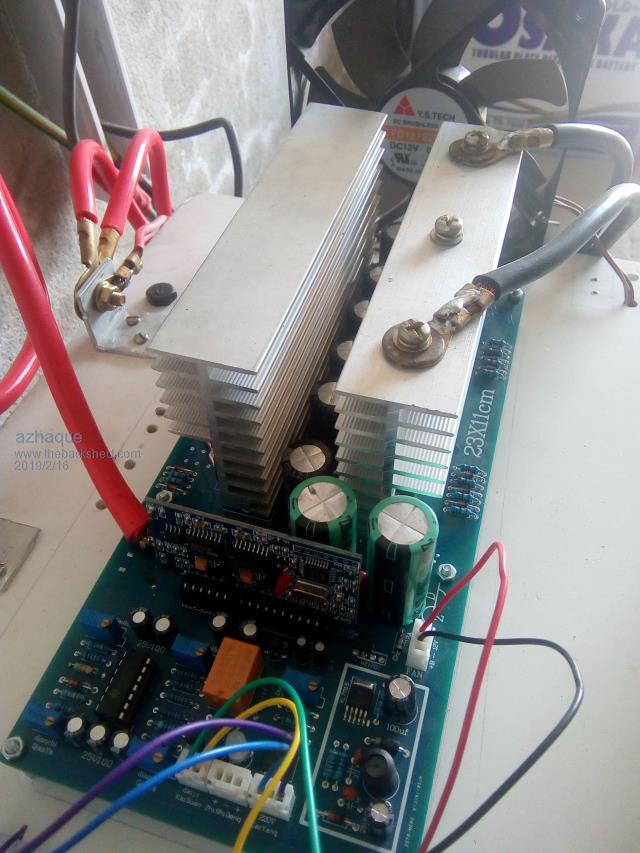 Volts, Amps and Hz. 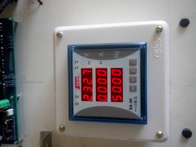 Inverter Board- Side view 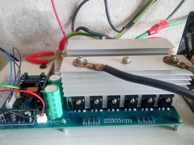 Transformer Cooling Fan 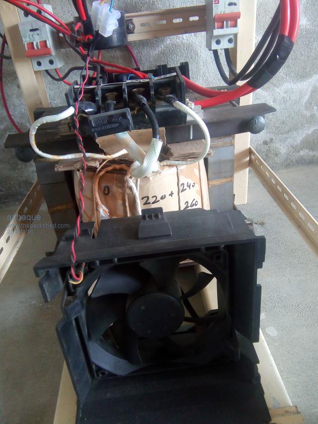 Transformer- Another view 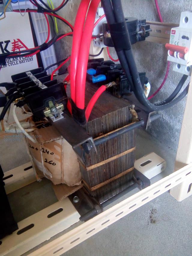 |
||||
| Warpspeed Guru Joined: 09/08/2007 Location: AustraliaPosts: 4406 |
There is certainly a bit of a learning curve involved, and I have tried to keep the explanation as simple and practical as possible. Quite a few eyebrows have been raised at the suggestion of using a steel cored choke for filtering out the 25 Khz ripple current. The usual accepted belief is that ferrite or some other type of low loss core material is usually necessary for switching power supplies that operate under similar voltage and similar frequency conditions. And that is usually the case. Chokes are very different things to transformers. For one thing, if its working properly, the current flowing will be almost dc with only a relatively small high frequency ripple current component. Its the high frequency rapidly changing current, and the magnetic field produced by that current that cause all the problems at high frequencies. Skin effect in the wire, and eddy current and hysteresis losses in the core are all caused by the rapidly swinging magnetic flux. Really big problems in a transformer, but a choke sees almost dc current flowing if the inductance is made high enough. Another factor is flux density. Our huge steel core will have a massive cross sectional area compared to a small switching power supply choke mounted on a circuit board. As the ac flux density reduces, as it will with greatly increased core area, so do the ac losses per unit of core volume. A small choke on a circuit board might get mighty hot with say half a watt of core loss, so we need to use a low loss core material if the core is small. Our huge steel lump may have several watts of core loss, which might produce a negligible temperature rise, and be completely lost in a multi kilowatt inverter. We gain vastly more in reduced switching loss in the mosfets than we lose in increased losses in the choke core. Some of those losses transfer directly to the choke, but we score a net overall gain in efficiency, so the choke loses go unnoticed and should be of no real concern. This can also be looked at from a different perspective. The choke and the primary of the transformer see identical current flow as they are directly in series. If we can keep the high frequency ripple current low in the transformer, it will also be low in the choke. If the transformer works efficiently using a laminated steel core that is efficient at 50HZ, so should the choke. If the choke is given sufficient inductance, both will be quite happy using the same type of laminated steel core material. Steel has two huge advantages for us. Its relatively cheap in large sizes, and it has a very high value of magnetic saturation compared to anything else. For us the ideal material would be grain oriented silicon steel C cores, these are the same material as our beloved toroids, but we absolutely must have a suitably large air gap. Cheers, Tony. |
||||
| BenandAmber Guru Joined: 16/02/2019 Location: United StatesPosts: 961 |
Warp speed thanks for all the info on chokes I've been taking a course online about inductors and they told me the exact opposite but I know who builds inverters and who teaches classes anyway I have pretty large C Core Transformer but the thickness of the lamination is going to be thicker they are grain orientated they're just a little older and a little thicker each layer and I was wondering just how big you're talkin about I also have toroidal cores 3 hundred watt core maybe 6 lb can a person cut one of those for an air gap thanks for your patience and thanks for all your awesome knowledge you're sharing be warned i am good parrot but Dumber than a box of rocks |
||||
| Page 1 of 2 |
|||||