
|

|
Forum Index : Electronics : Big arse volt meter.
| Author | Message | ||||
| Gizmo Admin Group Joined: 05/06/2004 Location: AustraliaPosts: 5078 |
I wanted a big volt meter I could read from a distance. My solar charge controller ( I'm off grid ) has a battery volts display, but its usually blanked, so I need to press a button to see the battery voltage, and needed to be standing in front of the controller to see the reading. All this involves walking across the shed from the doorway to the far wall, an exhausting 9 meter hike. I thought to myself, wouldn't it be nice to see the battery voltage from the shed doorway. Ebay to the rescue. I bought a set of five 70mm high seven segment LED displays for $10.96 delivered ( ebay 272097774437 ), and a 3 digit 2.5v to 30v meter for $7.95 delivered ( ebay 282303789536 ), and a universal step down regulator with a input of 60v for $6.79 delivered ( ebay 282605624430 ), plus a few bits from Jaycar. The 3 digit volt meter module has 3 wires, 1 sense wire, +ve and -ve. Its max supply voltage is 30v, but I discovered it can read up to 99.9 volts on the sense wire. This was a bit of luck, I had planed to use a 10:1 divider, as my battery voltage is 48v and I was going to calibrate it to read 4.8 volts and just move the decimal point. I removed the 3 digit LED display and probed the pins to work out what did what. The larger LED's require about 7 volts to light ( less for the decimal point ), so to drive the larger LED displays I used three LM324 quad op-amps. The volt meter module has a 3v regulator on board, so I used a couple of 1k resistors as a divider from this to provide 1.5 volts to the -ve inputs on all the op amps. Because my battery bank is 48 volts, I used the buck converter to step this down to 12 volts, which I used to power the op amps, LED's and voltage meter module. The buck converter is rated at 60 volts max, but my battery voltage can reach 62 volts at times, which may pop the buck converter. I replaced the buck converts two 100uF 63v input filter caps with a single 220uF 100v cap and a 0.1uF bypass cap, and connected 4 1N4004 diodes in series with the input to drop a couple of volts. This should give me a safety margin. Assembly is a mess, but its a one off and I was prototyping as I built it. The pictures tell the rest of the story. Happy with the result, I can see it from across the shed, and it only draws about 30 to 40mA with most of the segments on. The volt meter module. 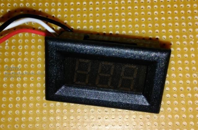 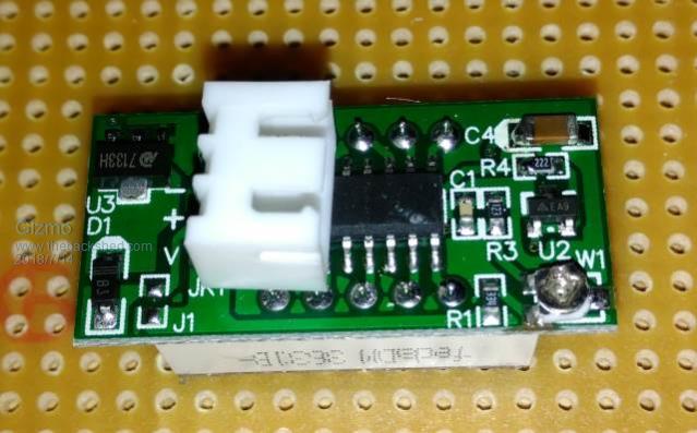 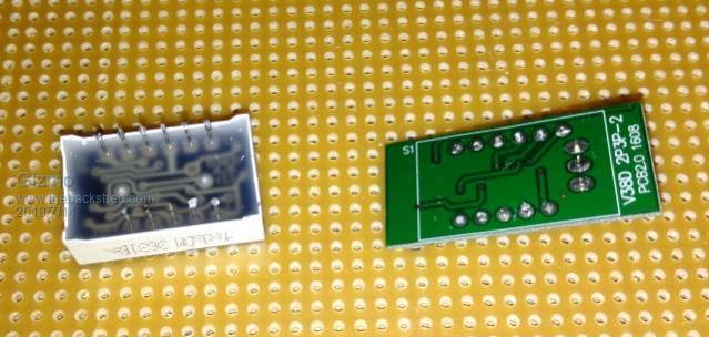 The big LED's 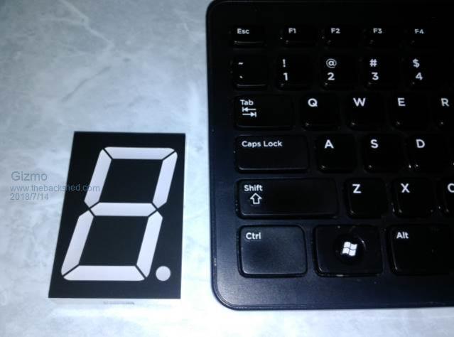 Wired up 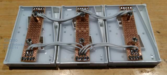 Buck converter. 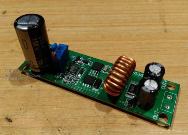 Messy mess. 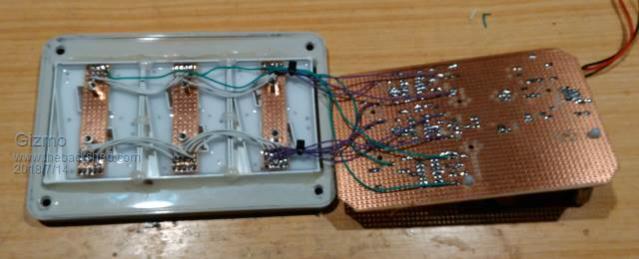 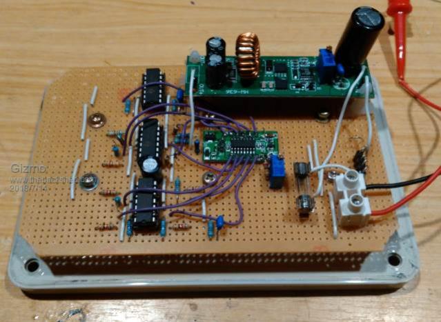 Calibration. 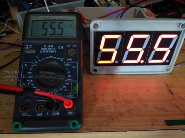 On the wall. Its high up, I can see it easily. 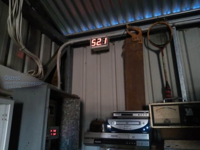 If anyone is interested I'll draw up the op-amp circuit. Glenn The best time to plant a tree was twenty years ago, the second best time is right now. JAQ |
||||
| greybeard Senior Member Joined: 04/01/2010 Location: AustraliaPosts: 161 |
Or for an analog solution, use the original display and a pair of binoculars  |
||||
| Ralph2k6 Senior Member Joined: 24/09/2017 Location: AustraliaPosts: 129 |
Brilliant. Upon initial glance I thought that you'd used an analogue volt to bcd chip (can't remeber the ic number). Made somthing similar years ago as a counter display, love those big cheap led digits. A guide to your circuit used would be great if you're happy to share. Very clever just jumpering off the back of the original LED outputs. Ralph |
||||