
|

|
Forum Index : Electronics : Current source inverter, blog
| Page 1 of 4 |
|||||
| Author | Message | ||||
| zaphod Regular Member Joined: 03/06/2018 Location: United KingdomPosts: 93 |
Not sure if this should be in solar or electronics anyway this is a new inverter I designed and I apologise forever that it is high frequency (ferrite). Today was a major upheaval removing the old equipment and installing the new having bench tested it thoroughly, well it almost worked!! But there is always a gremlin never mind how hard you try and in this case the new CSI is dependant on an external source for it's auxiliary power at 12V that drives it's electronics. This is supposed to be delivered by an existing hot-water boost converter but unfortunatly the new CSI's thirst exceeded the boost converters capacity so nogo today! But as they say tomorrow is another day and the boost converters APU is up for some modifications to increase it's output power. Here are some pretty pics of the installation so far, first on a wall under a permanent open sided lean too roof. Brown box on the right is the new CSI with it's AC isolator, grey box to the left is hot water boost converter with its DC isolator to it's left on the wooden beam. 2nd picture is the innards of the CSI box. Cheers Roger 1Kwp DIY PV + Woodburner + Rainwater scavanger :) |
||||
| noneyabussiness Guru Joined: 31/07/2017 Location: AustraliaPosts: 513 |
I think it comes down to whatever works for you with regards high frequency vs low frequency. .. if you don't need the surge capacity then high frequency is more than enough. .. Looks good and neat.. good job I think it works !! |
||||
| tinyt Guru Joined: 12/11/2017 Location: United StatesPosts: 438 |
Keeping an open mind here, hoping that you will share everything. |
||||
| ryanm Senior Member Joined: 25/09/2015 Location: AustraliaPosts: 202 |
Looks good zaphod. Is this a battery inverter or a GTI? |
||||
| Warpspeed Guru Joined: 09/08/2007 Location: AustraliaPosts: 4406 |
Always interested in something that is a bit different to the mainstream. Excellent work there Zaphod. Cheers, Tony. |
||||
| zaphod Regular Member Joined: 03/06/2018 Location: United KingdomPosts: 93 |
Thank you for your kind replies :) I am quite happy to describe my inverter, this is in fact the second generation the first having insermountable topological problems. With all my ECO gadgets I have economy in mind, that is they should eventually pay for themselves so I don't throw money at the problem, having also been a commercial designer of electronics for many years I have a fair handle upon creeping BOM inflation and cost control. As an aside this is a purely solar sourced inverter, there are no batteries at all. I prefer the monicer current source inverter or CSI because that's what it does, other words seem to over excite some people so I prefer to avoid them :) I consider the critical component of this design the transformer and I consider transformer coupling essential for safety even if it knocks a few percent off the theoretical efficiency. Hand winding a viable high frequency high voltage transformer is not easy as small quanteties of professional materials can rapidly get very expensive and if like me you do not make to many then surplusses typically go to waste, for that reason commercial litz wire is avoided. This immediatly places an upper limit on frequency as although it is possible to DIY litz my technique with an electric drill is limited to about 7 strands. Another major issue is creepage around the ends between primary and secondary the requirement being 4mm, this not only causes the useable bobbin width to be reduced, the requirement for a suitable high temperature spacer is hard to find and it just increases the difficulty of making the transformer. I decided to side step this issue by using Tripple Insulated Wire (TIW) for the secondary, this meets the re-enforced insulation standards without needing margins at the winding ends though I still use traditional transformer tape between primary and secondary layers more as a mechanical buffer than anything. It took a long time and many many spreadsheets to design the transformer however I found a very usefull program for knocking around ideas ExcellentIT7100 (beware where you download it from as usual) BUT dont take it's results literally check them :) For various reasons I will go into another time I do my sine modulation on the primary side, this means the transformer magnetics (flux density) has to be designed for peak power that is very nearly double the rms power but the copper content need only be designed for rms power. As a result of the magnetics being designed for peak the winding window is larger than required for the rms copper so they may in fact be run at a lower current density than normal as well as the extra window being usefull for fitting less than compact DIY windings. Finally leakage inductance is very very important, the windings are of sandwich construction (alternate primary and secondary layers) and the layers are designed to completely overlap each other (no half layers). Here are some pictures of the transformer under construction first is whole primary (in litz) wound on top of half secondary. 2nd is after that was taped up (get's progressivly lumpier with each layer unlike the pro's  ). 3rd is after 2nd half of secondary is wound, black wire is in fact TIW with heavy insulation. Last picture is completed transformer before application of Farady screen. I should add it's important to ensure winding end turns are adiquietly insulated and protected from abrasion, I use fiberglass tube, as it's often here the voltage stress is the greatest and choose the pinouts to ensure adiquite seperation and pcb layout (if your using one). ). 3rd is after 2nd half of secondary is wound, black wire is in fact TIW with heavy insulation. Last picture is completed transformer before application of Farady screen. I should add it's important to ensure winding end turns are adiquietly insulated and protected from abrasion, I use fiberglass tube, as it's often here the voltage stress is the greatest and choose the pinouts to ensure adiquite seperation and pcb layout (if your using one).Cheers Roger 1Kwp DIY PV + Woodburner + Rainwater scavanger :) |
||||
| Warpspeed Guru Joined: 09/08/2007 Location: AustraliaPosts: 4406 |
Watching this with very great interest indeed. My own system also uses switching power supplies to generate high voltage regulated +ve and -ve dc supply rails direct from solar panels. Its not dc isolated though. That powers a half bridge inverter directly without any battery during the day. At night dc power comes from a grid powered rectifier that provides slightly lower voltage +ve and -ve dc supply rails to the same inverter. At dawn and dusk, changeover is seamless as one dc supply slowly takes over more of the load from the other dc supply, as solar conditions permit. During changeover they both load share for a time. Very interested to see how you have done yours. Really good to see someone rise to the challenge of designing and building something totally different. Cheers, Tony. |
||||
| tinyt Guru Joined: 12/11/2017 Location: United StatesPosts: 438 |
Very good info zaphod. Way back I tried to understand a UPS appnote from microchip which uses ferrite transformers, gave up, could not follow their calculations. But what you are showing here is doable by a DIY'er, I think. Thanks for sharing, will be following with keen interest. |
||||
| zaphod Regular Member Joined: 03/06/2018 Location: United KingdomPosts: 93 |
Thankyou again everybody I like warps wire-or system (to use an old computing term) as he say's seamless and a very good way around the problem :) I want to say a few more words about that transformer, first I made a mistake! The leakage could be lower, can you see the bulge in the 2nd layer of the secondary in the 2nd picture ? well thats the end of the primary returning to its terminal Ugghhhh I allowed the pcb layout to drive the transformer pins!! Never do that again, it would have been better to return it over the top of the 2nd secondary layer or even better just terminate on a pin that side. However when doing a pcb layout for these things life gets difficult, I was using both top & bottom layers to get enough copper and also trying to maintain creepage & clearance (on the pcb). As it happens that was the 1st generation where the transformer was mounted on the pcb, well you might notice in the present incarnation it's chassis mounted, avoids soooo many problems BUT I am not about to rebuild that transformer, it just means the snubbers dissipate a bit more dealing with the extra leakage! For people making these transformers there are a few supply problems, first of all I use TDK/Epcos ETD cores, a major advantage is they are round, so much easier to wind in fact I cannot imagine making this trafo on a square bobbin BUT RScomponents have decided to stock German BLOCK square cores in preferance!! You can buy them at a price on Fleabay, anyway difficult to get hold of. Second problem is TIW, there are loads of people willing to sell you 100M+ at some god awfull price but very hard to source 10's of Meters(Yards), I just struck lucky with a nice guy in a distributor who had some offcuts on his desk. So the transformer design is not just what clunks out the end of a spreadsheet but also includes what you can actually get hold of material wise without breaking the bank! This transformer runs at 25Khz (skin depth 0.4mm) but guess what I happened to have 0.6mm wire so thats what the primary Litz is built from (8 wires) and the secondary TIW is 1mm copper (so only 0.8mm counts towards current density) but the actual od is 1.2mm (0.1mm thick insulation). I am sorry about all the metric stuff but sadly the UK got metricated sometime in the 70's and it's no longer possible to deal with UK suppliers in imperial but for USA suppliers I have to do the mental arithmatic pretty quick  A few more details to help the transformer make sense, it's design peak power is 2Kw, ratio is almost 4.5:1, it is an ETD54 core of N87 material, input is from a half bridge operating from a nominal 180V supply. I hope to continue with more in a few days but ATM a bit bogged down in debugging some problems, I found today an old heater cable that where it passed through a clamp on said heater had melted (despite being high temperature cable) and devoloped an earth short (thank god it wasn't the heater element). The other problem is the CSI processor is so damm thirsty the solar system doesnt like powering it up from cold, works fine from a bench supply of course (don't they all) hoping to fix that one in software hahaha I want to say how impressed I am with this site, people doing DIY things  Cheers Roger 1Kwp DIY PV + Woodburner + Rainwater scavanger :) |
||||
| Warpspeed Guru Joined: 09/08/2007 Location: AustraliaPosts: 4406 |
Really fascinating Zaphod. I have built quite a few forward converters but never very successfully at really high power. Its a far more complex and difficult problem to design the magnetics than just making everything bigger, so I am really admiring your work. My own way of doing this is my own rather unique flyback topology, which although requiring a much larger core and probably more copper (for only 1.6Kw). It solved a lot of the problems and has the advantage that both input and output voltages are not rigidly tied to the turns ratio. It can also very gently start up from a low voltage high impedance solar source at sunrise, and gradually start transferring smoothly increasing power from almost nothing right up to full maximum grunt. The dc input voltage can be below, equal to, or much higher than the regulated dc output voltage. Easy to do with flyback, much more difficult with a forward topology. My transformer is also very different to yours. Mine uses a very large gapped U/I core with two 18 turn interleaved foil windings wound around the U. Really easy to make, and it gives outstanding results at 20Khz. Cheers, Tony. |
||||
| zaphod Regular Member Joined: 03/06/2018 Location: United KingdomPosts: 93 |
Hi Warp many thanks again for the kind comments, 1.6Kw is pretty cool too and I guess your input is lower voltage than mine hence the tape, perhaps 12-48V ? Flyback is good for stepup but the copper and core utelisation is a bit poor. Actually at 2Kw I reckon I am on the limits for half-bridge too as the capacitive other half of the bridge is a bit stressed even at 180V input. Yup you would have to have a large gap and that has it's own problems namely fringing flux that I was going to move onto another day :) I fixed the processor startup current as expected in software by running it at just 0.03Mips for the first 20 seconds before ramping up to presently 40MIPS for normal operation, this is not a big deal as it only happens at dawn :) Things are going quite well for the CSI's 1st field trials, some voltage regulation problems but hell I just discovered I made another big RADIO TRANSMITTER!! Attached pictures show my before and after broadband tonel SNR's and basicly the gadget knocks out everything at the HF end as well as blotting out medium wave radio high end!! Funny how nothing bad showed up during bench testing but thats what field trials are for :) Used all my junkbox ferrites on the last job so top up stock now in order. 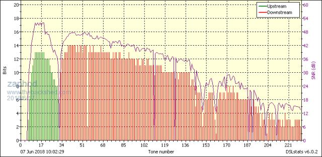 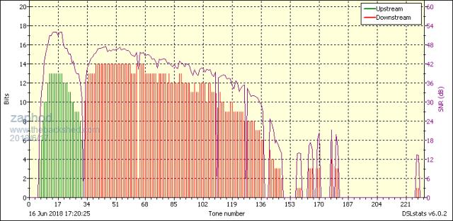 Cheers Roger 1Kwp DIY PV + Woodburner + Rainwater scavanger :) |
||||
| Warpspeed Guru Joined: 09/08/2007 Location: AustraliaPosts: 4406 |
My input is actually quite high, eight 24v panels in series. And I have three groups of these panels, and three 1.6Kw dc to dc converters. Open circuit solar panel voltage around 280v, max power output at about 220v. My two output rails are +/-225v dc. Yes the copper and core utilization are horrible, the air gap is huge and it certainly fringes very badly around the gap. But the trick seems to be keeping the gap and fringing well clear from the windings. The windings themselves are lovely ! Absolutely minimal leakage inductance, no spikes and no ringing. I can draw 1.6Kw from either output rail and nothing from the other. The cross regulation is superb, only about one volt difference between rails at the most extreme load unbalance. That is necessary because my inverter is half bridge and draws power from each dc rail alternately each 50Hz half cycle. But the cross regulation worked out much better than I ever dared hope for. I have learned some very interesting things from much trial and error and experimentation with the magnetics with this. Placing the gap in the middle of the winding is a total disaster in a flyback supply, although everyone does this usually using identical core halves. Its the fringing that causes all the ringing and crap on the voltage waveform. Keep the gap and its fringing well clear of the winding, and all of that just goes away. The other thing is using interleaved copper foils with 1:1 turns ratio is absolute magic, and reduces leakage inductance to practically zero. And its so easy to wind something like that. My several various attempts at building high power forward converters with litz wire have not been quite so happy. Anyhow, this is huge ugly and although electrically efficient is o/k for home brewing, but would be a disaster commercially. But it has been fun and very instructive. Good luck with the EMC testing, I retired some years ago and escaped most of that. EMC testing has certainly complicated the life of power electronics engineers. Cheers, Tony. |
||||
| zaphod Regular Member Joined: 03/06/2018 Location: United KingdomPosts: 93 |
Well as we were on the subject of fringing flux I will show you my solution  The output of this inverter consists of an LCL filter, as previosly mentioned sine modulation is carried out on the primary side so the first L operates in both discontinuous and continuous modes hence it's ripple currents can be very high. Consiquentially it is wound in Litz and is an gapped ETD core (N87 again) as no sensible ring could both provide the inductance and be of a low enough loss. A problem aluded to by Warp is the gap is designed to be entirely in the centre pole under the winding and without some management will cause winding heating. In my case I made a spacer in the bobin to force the winding clear of the gap (see 1st pic), wire is just retention while the glue sets. The completed inductor is in 2nd pic. P.S. Any pics of your transformers Warp ? Would love to see  Cheers Roger 1Kwp DIY PV + Woodburner + Rainwater scavanger :) |
||||
| Warpspeed Guru Joined: 09/08/2007 Location: AustraliaPosts: 4406 |
Now that is really interesting. Sine modulation on the primary, rather like PFC. And the spacer around the gap is a very original idea too. I have never seen that done before anywhere, but it does make a lot of sense. Will be fascinated to see how you turn that back into low frequency ac. I am really enjoying this thread and your project. Not many true innovators or truly original thinkers out there on the hardware side these days. But there are still plenty of challenges for those that are really interested in innovation and trying out something different. Don't have a picture here right now. Its the middle of winter down here in oZ, dark and cold right now outside. Will venture out to the shed tomorrow with my camera. This particular dc to dc power supply of mine has a few rather original ideas in it that I think you might find interesting. So as someone once said about something completely different: "I will show you mine if you show me yours". Cheers, Tony. |
||||
| zaphod Regular Member Joined: 03/06/2018 Location: United KingdomPosts: 93 |
Hi Warp funny to think of someone in winter when its over 18C outside here :) I was to slow in editing the post I meant to show a shot from my trusty saturation tester but it got purged I think! This is another component originally made for the 2017 project but got rescued and incorperated in the 2018 one. Best I have is the picture here that I am fairly sure is this inductor, vertical scale is 4A/div so saturation ~12A this is a 500uH inductor. 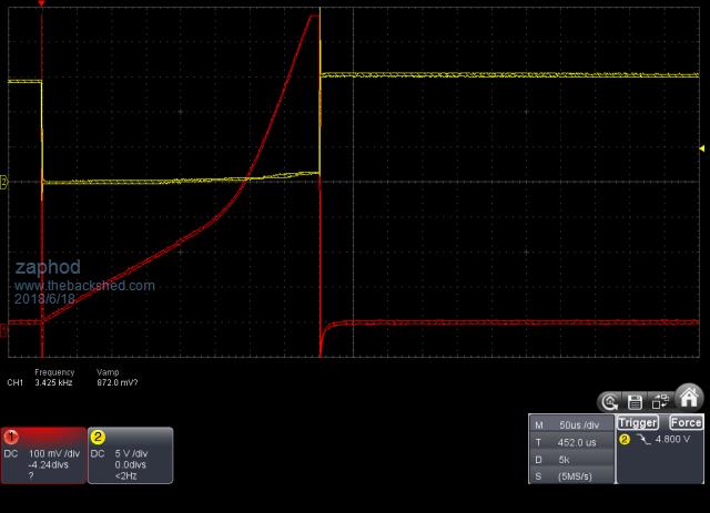 Now I am getting really really interested in your backshed project too  Yes this on is exactly like a PFC although I didnt think of that before I started, I just wanted to avoid high frequency modulation/switching in the HOT side of the inverter. Yes this on is exactly like a PFC although I didnt think of that before I started, I just wanted to avoid high frequency modulation/switching in the HOT side of the inverter.The first thing that happens after the transformer secondary is a bridge rectifier so the output of that is unipolar  You cannot see the low frequency at this stage because it's buried in the HF mush, thats what the LCL filter does, demodulate it! You cannot see the low frequency at this stage because it's buried in the HF mush, thats what the LCL filter does, demodulate it!I use LTspice heavily for simulation I will practice uploading here so I can show more of the development process  2018-06-18_194006_Basic_Buck_LCL.zip Ahh seems to work, ok if you run that one and look at the current waveform through V5 you can see how non-linear it is  This is however the basic topology of this design. This is however the basic topology of this design.I agree about hardware original thinking, I have a few patents as well but nobody needs us any more they just copy and cost reduce something they already have access too hahha. I am also retired thank god, no more company politics.....hooray  Cheers Roger 1Kwp DIY PV + Woodburner + Rainwater scavanger :) |
||||
| Warpspeed Guru Joined: 09/08/2007 Location: AustraliaPosts: 4406 |
It sounds like we have a very great deal in common, retirement is great for tinkering around with off the wall unconventional ideas without being distracted by real work. I don't have Spice here, never really bothered much with it. It seems problems are either trivial enough not to require it, or so complex the parasitics and "unknowns" cannot really be modeled easily. Its a great teaching aid though, but it does have its limitations. A while back, I built myself an inductance tester to create a saturation curve just as in your picture. It used the half bridge diagonal topology so that the stored inductive energy was almost all completely fully returned to the dc rail. Its astonishing to see current peaking out at sixty amps or more, yet only drawing a couple of amps of make up power from a bench power supply to keep it running. There is a thread here somewhere about that. Anyhow, several people on this Forum built their own similar inductor testers with great results, and had quite a bit of fun testing some high current chokes for the low voltage PWM transformer inverters, which is all most people on this Forum are really interested in. Now your inverter is particularly interesting, because you are feeding PWM through a transformer and a choke, and nobody else does that. Its going to be seriously difficult to design that transformer, but it seems you are well on your way to achieving that. Serious stuff indeed. My own dc to dc topology is rather unusual, but so were my requirements. I needed two very well regulated dc output rails with really good cross regulation. The input being from high impedance solar panels could be either below or above the required output voltage. Here is a very simplified schematic of my first attempt which has been running for two years and is still working right now. 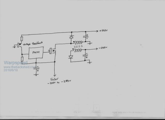 This works very well, but there were a few things I did not like about it, especially the whole control system running at a very dangerous voltage. But the magnetics worked amazingly well. The waveforms are text book perfect, so the next version had the whole control system at ground potential, and the mosfet gate driven through a third trifilar winding so that the gate drive needs no galvanic isolation. 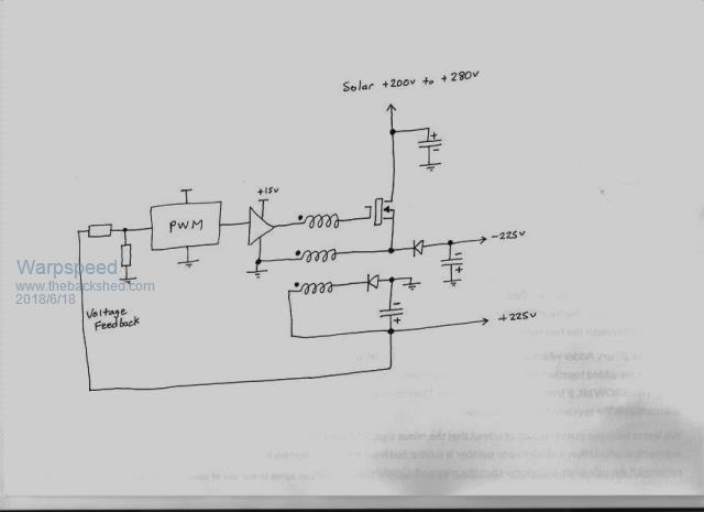 I have never seen anything like this before, but I have tested it thoroughly and had it running for a while under load, without any problems at all. The primary winding is three .005" foils making it a .015" foil. It supplies all of the input power, and half the output power. The lower secondary is one .005" foil because it only supplies half the total output power. The gate winding is a fine wire, a piece of teflon insulated wire wrap wire. It not only works, but works extremely well. Cheers, Tony. |
||||
| zaphod Regular Member Joined: 03/06/2018 Location: United KingdomPosts: 93 |
Sorry for not posting pictures of the actual data.....1st is spice schematic, 2nd is V5 current for three different values of LO. I should add the schematic is grossly simplified to have any hope of completing a grid half cycle this century on my computing resources hence the use of a switch instead of real mosfet etc etc 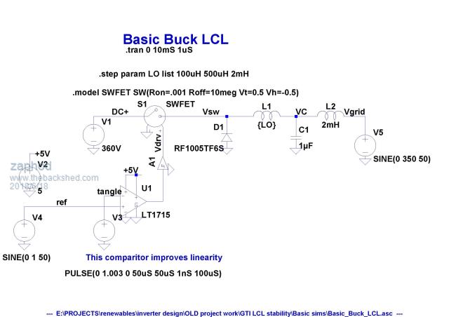 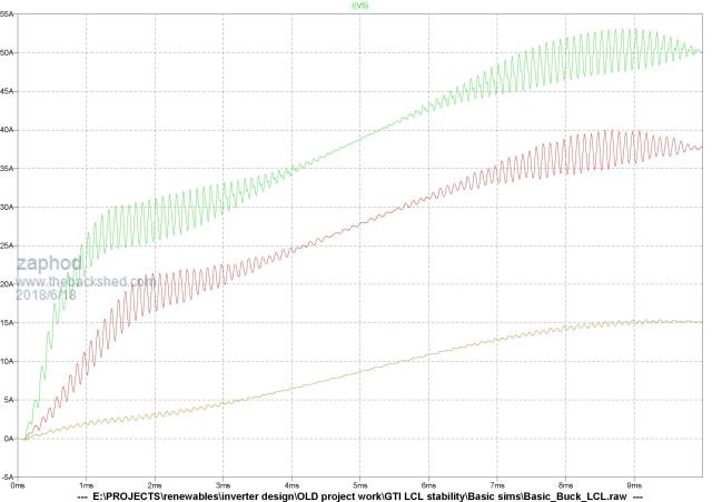 I love your topoligy, simple and effective though like you say the 1st has the ouch! factor  I know from hard experience how hard it is to debug stuff like this so always try and keep the bulk of the control stuff near earth. I guess you hade some hefty lumps of ferrite and some foil left over from somewhere, bet that trafo is just as clean as you say as long as you could get someone to lend some extra hands during winding, I once used a door handle and was halfway through winding when someone opened the door (inwards towards me) I know from hard experience how hard it is to debug stuff like this so always try and keep the bulk of the control stuff near earth. I guess you hade some hefty lumps of ferrite and some foil left over from somewhere, bet that trafo is just as clean as you say as long as you could get someone to lend some extra hands during winding, I once used a door handle and was halfway through winding when someone opened the door (inwards towards me)  My saturation tester isn't that sophisticated but it's good to 50amps or so, I only do single shot testing so the bench power demand is small anyway. It has an overcurrent trip that stops it damaging itself or the UUT so no timing twiddling just a single button push. Usefull to get a handle on inductance too from measuring DI/DT on the scope. The main reason I use Spice is to be able to visualise things that are otherwise lost in too much mathmatics, like that LCL filter for example, once you try linearising it by putting a feedback loop around it things get really hairy and its good to see the resonances and magnitudes rather than just raw numbers IMOP could be just my brain is more childlike (pictorial)  That negative rail Nchannel mosfet drive is amazing, very original and simple certainly activates some braincells hahaha Back to gardening, sun is out, loads of plants to pot up this afternoon and no ferrites to play with yet (EMI). Cheers Roger 1Kwp DIY PV + Woodburner + Rainwater scavanger :) |
||||
| Warpspeed Guru Joined: 09/08/2007 Location: AustraliaPosts: 4406 |
The first topology I tested and developed with a non standard power supply arrangement so that the control system was at ground potential, but it was very inconvenient, and an ugly solution. You are quite right about me already having the giant ferrite U cores, they are far too expensive to buy new. But I have a giant pile of assorted ferrite bits and pieces here, accumulated over many decades of professional R&D. Its definitely not elegant or efficient from the size or core utilisation aspect, but I don't care about that. Its quite power efficient though, and because its a 20Khz discontinuous mode flyback the feedback is very easy to apply. Current peak at full power is around 35amps which is not too bad. I run three of these fed from three separate banks of solar panels. Not shown on the circuit is am MPPT input voltage feed forward system that over rides the voltage feedback so the panels can never be overloaded in poor sunlight. The second version only ever reached prototype form, I have since gone off in a completely different direction altogether, with something even more strange and radical. More about that later. Your LCL filter is going to introduce some interesting complications with feedback loop stability, as will the sudden change in mode between continuous to discontinuous choke conduction. I hope you are well set up there to tackle those kinds of problems. A cost effective Bode plotter is another long term project on my wish list. I have it all worked out how to do it, just received an e-bay HP3580A spectrum analyser yesterday in fact, as part of that. What do you use to solve the feedback gain/phase problem ? Cheers, Tony. |
||||
| Warpspeed Guru Joined: 09/08/2007 Location: AustraliaPosts: 4406 |
Here is a rear view showing the three flyback chokes. The 3mm sheet rubber air gap is well clear of the windings which I think is probably why they work as well as they do completely free of voltage spikes or ringing. The fringing is so bad I had to use plastic rod to mount the ferrite cores. long steel bolts quickly heated up to soldering iron type temperatures and started to smoke. The bundle of black wires are from the solar panels that face in four different directions. East, West, North, and straight up. 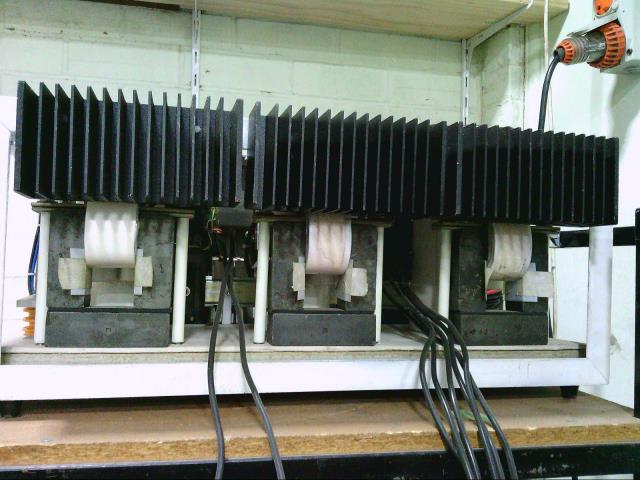 Not really much to see from the side, its pretty simple. 1:1 flyback choke with 18+18 turns of interleaved copper foil. 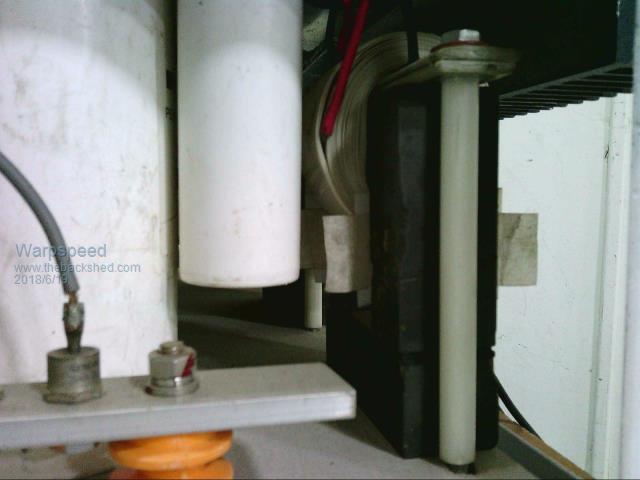 The original (deadly) circuit board that is running at the moment with a single mosfet and a small 15v isolated dc supply (SM-015) sitting up in the air next to the mosfet. 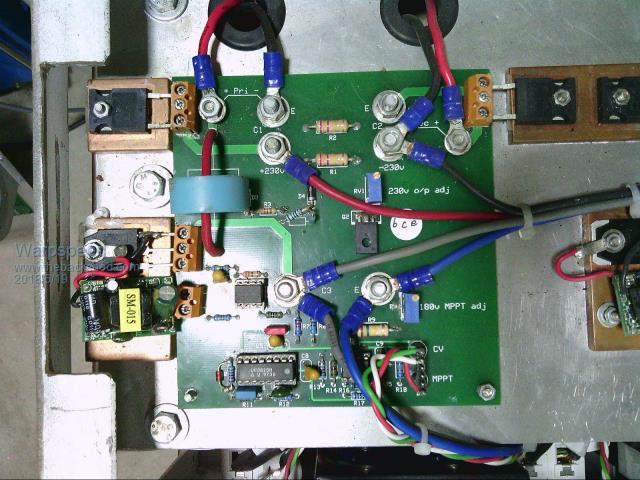 The new prototype with potentially two mosfets, to lower conduction losses and better spread the heat flow. The yellow wire is the experimental gate drive wire which works much better than I ever dared to hope. 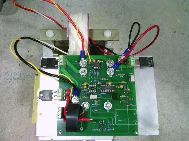 Cheers, Tony. |
||||
| zaphod Regular Member Joined: 03/06/2018 Location: United KingdomPosts: 93 |
Woww warp those are great pictures, umm 6mm total gap!! did you ever measure saturation (I am guessing off scale) ?? Thats what I call massive ferrites, makes my stuff look like it came out of toytown  Going by the insulators and crimps I guess you used to work professionally in motor drives maybe ? I used to design communications processors including FPGA code, PCB draughting and nececeraly some power supplies. I see you got nice big TO247 packages something I need for high voltage but did not have the space for (to many devices) so struggling with creapage & clearance on TO220! I don't see any current transformers or shunts anywhere but of course solar source is self limiting as far as continios current is concerned but I am guessing there are some BIG (as there not on the pcb) input bypass caps somewhere Going by the insulators and crimps I guess you used to work professionally in motor drives maybe ? I used to design communications processors including FPGA code, PCB draughting and nececeraly some power supplies. I see you got nice big TO247 packages something I need for high voltage but did not have the space for (to many devices) so struggling with creapage & clearance on TO220! I don't see any current transformers or shunts anywhere but of course solar source is self limiting as far as continios current is concerned but I am guessing there are some BIG (as there not on the pcb) input bypass caps somewhere  very very neat construction and nice pcb's very very neat construction and nice pcb's  Whilst waiting for ferrites I have been thinking increased EMI is probably a downside of chassis construction and resulting long switching current loops OTH big magnetic components consume a lot of pcb space. Do you guy's there get internet down your phone lines like me or are you lucky and have fibre (maybe radio) ? I ask because thats my major EMI problem as I live in a rural area on a very long copper line, almost at the limit of working. Lots of people model feedback loops in Mathcad as they give it away to students but not retards like me and it's very expensive. So I make do with LTspice because it's free but nowhere near the sophistication level of Mathcad so you have to make all sorts of weird models that don't look like the circuit your trying to simulate just to get results from it. You can of course calculate simple things like resonant frequencies but the interaction of many components is beyond calculation IMOP. So I do a lot of modelling before I go near a soldering iron for this type of design prefering not to have to keep physically changeing the circuit. It is possible given time to make fairly accurate models of most things but if the models are excessivly accurate the simulation time of a complex circuit can be many many hours only to discover you did something stupid and have to start over ! Consiquentially I make most of my own models rather than use libraries. Guess I got used to heavy simulation for large FPGA's that I used to design that were functionally tested in simulation as they were to complex to test in real hardware. You asked about phase margin, well frankly I have not found a way to directly measure or simulate this in this very dynamic circuit, instead I concentrate on phase lag or group delay and resonances, I guess the margin before resonance is effectivly phase margin and all I can say is after a lot of work it is adiquite for all operating conditions though I could not numerically express it. Cheers Roger 1Kwp DIY PV + Woodburner + Rainwater scavanger :) |
||||
| Page 1 of 4 |
|||||