|

|
Forum Index : Electronics : Sine wave to ttl square wave
| Author | Message | ||||
| Rubes Newbie Joined: 01/05/2009 Location: Posts: 36 |
Hi I have an anometer that that puts out an AC sine wave signal induced by rotating magnet on propeller shaft. 80 mV p-p at 100 rpm. 8.0 V p-p at 10,000 rpm. Output Frequency 3 per revolution(0.098 m/s per revolution. I need to convert the sine wave to a ttl level square wave to use with an arduino logger and after much searching found this  which I gather should feed to this  taken from here Question is would this achieve what I am after given the range of the anometers output voltage. Thanks in advance |
||||
| davef Guru Joined: 14/05/2006 Location: New ZealandPosts: 499 |
Rubes, Read the link and looks reasonable. What Vcc and Vee is recommended? Having to produce an negative supply is a little bit of a hassle. Are there any "single-ended implementations? If Vcc and Vee are say 5Volts I would be concerned about what happens with an 8V p/p input. If the LM339 has input substrate clamp diodes then you will want to limit the input current, if it doesn't then maybe you need to "pot-down" the input signal. See if there is an input current specification. I guess the only issue with the 74HC86 is that you will get two pulses per cycle, which you can take care of in software. |
||||
| Warpspeed Guru Joined: 09/08/2007 Location: AustraliaPosts: 4406 |
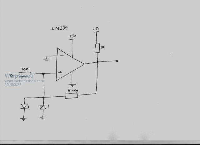
Rubes, you can use a very similar circuit that overcomes the high voltage at high rpm problem, into the LM339 by connecting a series resistor and a couple of back to back shottky diodes to the input of the LM339. In fact if you do that, the LM339 will work fine from just a positive power supply voltage. Its also a good idea to add a very small amount of hysteresis with a high value resistor between the output and the non inverting input. Something like this perhaps:  Cheers, Tony. |
||||
| Rubes Newbie Joined: 01/05/2009 Location: Posts: 36 |
Yeh just been looking at the hassle of suppling neg rail, it does not metion the recomended Vcc Vee. Suspect a single ended implementation may cause problems ( could maybe make Vcc/Vee 12 v and deal with it after with some level shifting?, will look into your other concerns, a bit over my head as never dealt with opamps before. Thanks for your input and am open to any other suggestions. Oh just seen Tony's input do you think pos input only would be an issue see original article here |
||||
| Warpspeed Guru Joined: 09/08/2007 Location: AustraliaPosts: 4406 |
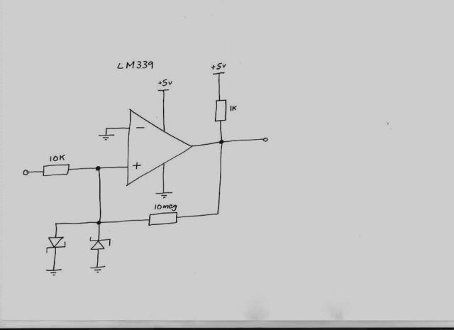
Single ended implementation will work fine, as long as the input does not go more than 0.6V below the most negative supply. If the most negative supply is ground, shottky diodes will turn on hard well below 0.6V so that eliminates the problem. The LM339 will never see more than a few hundred mV +ve or -ve at the input. With a 10K input resistor you could easily drive that circuit to many tens of volts in either direction without any problems, and with only a positive 5v supply. This definitely does work, I have done it many times. I stuffed up drawing the symbols for the shottky diodes, what I actually drew were zener diodes. The schematic should really look like this :  Cheers, Tony. |
||||
| Rubes Newbie Joined: 01/05/2009 Location: Posts: 36 |
Thanks guys for the input will give that a bash Tony as soon as I can get the parts together |
||||
| Rubes Newbie Joined: 01/05/2009 Location: Posts: 36 |
Oops more questions, any idea of what schottky's to use and given that Tony's circuit above is single ended I presume that the output wave form would be too ie positive (or am i wrong) so do I even need the 74hc86 given that I really need a 50% duty cycle of at least 10uS to capture to microprocessor and if I do need it how to calculate R1 and C1 to give this. Just gets more complicated.  |
||||
| Warpspeed Guru Joined: 09/08/2007 Location: AustraliaPosts: 4406 |
A 1N5711 from Jaycar or Altronics would be a suitable small low power shottky diode, but almost any shottky diode would work in this application. http://pdf.datasheetcatalog.com/datasheet/hp/1N5712.pdf These turn on at around 340mV, so the LM339 never sees more than +/- 340mV on the input pin, no matter how large the incoming voltage may get. Its perfectly o/k to swing the input of the LM339 slightly below ground, as long as its less than 600mV below ground, and you will be well below that limit. The output of the LM339 will be directly TTL and CMOS compatible and switch from ground right up to the full +5v supply. Not sure why you wish to add the 74HC86 frequency doubler, if this is driving a microcontroller, its not needed. The output will be a 50% duty cycle except when the input voltage is extremely low, perhaps only a very few millivolts. In that case the logic high will be a bit longer than the logic low. Over about 10mV rms input, its going to be an equal 50% in either direction. With zero input, and the input fixed at ground potential the output will sit permanently logic high. It will give a very clean well behaved output. Its a really nice circuit. Cheers, Tony. |
||||
| Rubes Newbie Joined: 01/05/2009 Location: Posts: 36 |
Thanks again |
||||
| Rubes Newbie Joined: 01/05/2009 Location: Posts: 36 |
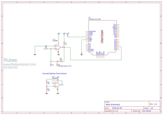
ok just trying to figure out the termination of the 3 unused opamps and this seems to be the the safest way (circuit at bottom of drawing)  Dumb question but can I use the same voltage divider on the other unused opamps or do i need one for each of the 3 unused. Its going to be a while before I can test the circuit as some parts coming from you know where which will give me some time to get my head around opamps. |
||||
Madness Guru Joined: 08/10/2011 Location: AustraliaPosts: 2498 |
LM339 has 4 separate circuits apart from ground and VCC. The data sheet gives a detailed circuit of each. There are only 10 types of people in the world: those who understand binary, and those who don't. |
||||
| Rubes Newbie Joined: 01/05/2009 Location: Posts: 36 |
Yep but my dumb question is can one voltage divider feed 3 opamps since they have common grd and vcc ie basically the same wiring as in above drawing for each opamp but with one voltage divider feeding all 3 inputs. |
||||
| Rubes Newbie Joined: 01/05/2009 Location: Posts: 36 |
Better image here 2018-03-30_135752_lm339_Sine_to_Square_Wave_TTL_v2.pdf |
||||
Madness Guru Joined: 08/10/2011 Location: AustraliaPosts: 2498 |
What would be the point of putting the same input in 4 times? There are only 10 types of people in the world: those who understand binary, and those who don't. |
||||
| Rubes Newbie Joined: 01/05/2009 Location: Posts: 36 |
3 opamps of the quad chip are unused and as per here and here I need to properly terminate them so what I am asking is if one voltage divider can feed all 3 unused opamps so as to properly terminate them or do i need 3 separate dividers. Thanks |
||||
| davef Guru Joined: 14/05/2006 Location: New ZealandPosts: 499 |
I wouldn't use the term terminate, however my understanding is that you want the unused op-amps or comparators to remain stable. I connect the output back to the negative input. Optionally, you can ground the positive input as well or as you have seen just connect three unused positive inputs to your to the fourth input. The reference is lost in the mists of time. |
||||
| Rubes Newbie Joined: 01/05/2009 Location: Posts: 36 |
ok I think I am showing my ignorance, apparently the lm339 is a comparitor not an opamp and the all unused inputs should be connected to ground, apologies. |
||||
| Rubes Newbie Joined: 01/05/2009 Location: Posts: 36 |
Right, more confused than ever, if it states anything at all the datasheets from lm339 manufactures say to tie any unused inputs to negative. does this mean ground for a single ended supply or is it to neg supply which I dont have. |
||||
| Warpspeed Guru Joined: 09/08/2007 Location: AustraliaPosts: 4406 |
Connecting the unused inputs to ground is just good practice. Nothing bad is going to happen if you leave the unused inputs completely unconnected. By the way, the LM339 has four identical comparators and comes in a 14 pin chip. There is also the LM393 which has only two comparators and comes in an 8 pin chip. All these comparators are electrically identical, so you could use either type of chip. Cheers, Tony. |
||||
| Warpspeed Guru Joined: 09/08/2007 Location: AustraliaPosts: 4406 |
How is this coming along Rubes ? Cheers, Tony. |
||||