
|

|
Forum Index : Electronics : ozinverter control no sinewave
| Page 1 of 11 |
|||||
| Author | Message | ||||
| johnmc Senior Member Joined: 21/01/2011 Location: AustraliaPosts: 282 |
Good day All I am building a ozinverter using clockmans powerboard and controlboard, the problem is that when testing the control board there is no sinewave output at the low IR2110, but a square wave @ 50 Hz which is amplified version of the EG8010 output pin SPWOUT2. There is no sinewave output at the high IR2110 but a square wave of 23.4 KHz also a amplified copy of the EG8010 output pin SPWOUT4 I am using EG8010 version HN1518HT1536 control chip. I have tried 4 EG8010 chips all of the same version and all give the same result Also have replaced the IR2110 chips also no change . I have been stuck on this problem for many days and have exhausted my meagre talent. Am I correct in assuming that the sinewave is generated in the 2110, and the associated capacitors? How do you attached pictures?. cheers john johnmc |
||||
Madness Guru Joined: 08/10/2011 Location: AustraliaPosts: 2498 |
Hi John, You will not see a sinewave as such until the control board is connected to the power board and the signals have combined together in the transformer. The pins marked 5 & 6 will both have squarewave signals and 7 & 8 will have the fuzzy SPWM signal. 5,6,7 & 8 are the signals coming from the EG8010, so if you have these signals the EG8010 chip is working but it will be shutting down after 3 seconds as it is not detecting any voltage feedback. If you just have the power board powered up on its own you will get a square wave on the IR2110 on the pin marked 1 in the diagram below, 2 will have a very weak barely visible output, 3 will have a fuzzy wave that is the SPWM(sinewave pulse width modulation) pin 4 will also have a barely visible signal. If there is no out put at all from the IR2110 check that the 13V power supply is working. 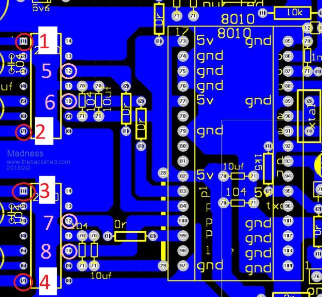 Pins 2 and 4 are not showing any signal at this stage as they need voltage coming back on the 2 middle pins of the main 10 pin connector. For initial testing of the power board it is by far best to not have the 6 10,000uf capacitors installed and to have around 30 ohms >20W resistance in series on the power supply. The reason for this is that the resistance will limit the energy available and prevent the MOSFETs from failing if there is a fault. The Capacitors must not be fitted also as they store enormous amounts of energy that will cause damage if something is wrong. So once you confirmed the signals are correct as per the second paragraph connect the power board as described above. You will need to remove the earth pin on the power to your Oscilloscope for the next tests. With everything connected with no capacitors and the resistance in series voltage feedback etc all connected you can then connect the CRO across the AC output of the transformer (toroid). Have the CRO turned on and turn on DC power to the inverter, then turn on the switch on the control board. All going well you will get a sinewave output on the CRO, it may be slightly distorted at this stage and the EG8010 most likely will shut down due to low voltage (4 flashes) be aware that it will try again so don't touch the AC output until everything is shut down. If this is successful remove the 30-ohm resistance and connect DC power via a low current breaker 10 or 20 amps, you will get away with using a 240V ac breaker. Now the inverter should power up and keep running with a nice clean sine wave, you will most likely need to adjust the voltage pot on the control board to around 220 to 230 volts. Now you can put the capacitors in the power board and assemble the inverter ready for use. To upload an image use the 2nd button from the right below the word colour above the reply text box. Let us know what you get at each stage. There are only 10 types of people in the world: those who understand binary, and those who don't. |
||||
| noneyabussiness Guru Joined: 31/07/2017 Location: AustraliaPosts: 513 |
John, Madness has explained it very well and simple ... Ive always been one to try and understand whats happening underneath as best as possible. . The eg8010 chip creates the " sinewave " with a higher frequency pwm ( 23.5 khz ) hence the term SPWM ( sinsoidal pulse width modulation )... the 50 hz square wave you are seeing is what is called " unipolar modulation " so only 1 side of the H Bridge creates the wave shape with high frequency pulses, the other the basic frequency of 50 hz. .. Filtered correctly the transformer only sees the " fundamental " frequency which in most cases here it 50hz... I think it works !! |
||||
| johnmc Senior Member Joined: 21/01/2011 Location: AustraliaPosts: 282 |
Good Day, Madness and noneyabussiess Thanks for the above information, which is much appreciated. I will be trying tomorrow, to make the inverter sing. will keep you informed. Cheers john johnmc |
||||
| johnmc Senior Member Joined: 21/01/2011 Location: AustraliaPosts: 282 |
Good Day, Madness and noneyabussiess Thanks for the above information, which is much appreciated. I will be trying tomorrow, to make the inverter sing. will keep you informed. Cheers john johnmc |
||||
| johnmc Senior Member Joined: 21/01/2011 Location: AustraliaPosts: 282 |
Good day all. My Ozinverter up date, Connected up the inverter , with no large capcitors on the power board, and 25 ohms restriction to the 48v suppy inverter would start for about a second the stop and then repeat . Removed the resistor and placed a 1 amp capacity lead in its place. Inverter started and ran almost silent, output voltage could be adjusted between 210vac to 270va set the voltage to 230vac  All smiles. All smiles.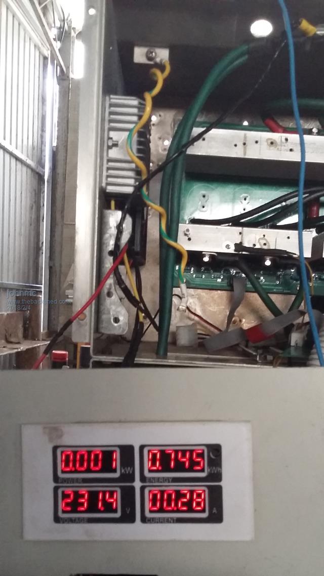 The fet heat sinks felt warm to touch. then I remember that the power board was set up with 5R6 ohms on the fet driver and for the EG8010 controller and Oztules had that the fet driver should only be 4R7 ohms or the fets will overheat. After about 10 minutes a wiff of smoke then fizzy sound then the metalized 4.7uF capacitor on the mainpower board blew the end out.  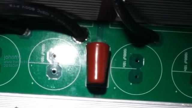 Have ordered some 4r7 resistors and hope this allows the saga to continue cheers john johnmc |
||||
Madness Guru Joined: 08/10/2011 Location: AustraliaPosts: 2498 |
I have seen everything else fail but never one of those red caps. Good to see it fired up for you did you have your CRO connected to the AC out? The fact that it ran quite is a very good sign, if the wave form is wrong it will make horrible sounds. It should be running fine with 5R6 gate resistors, could be you have a dodgy FET in there. Were all the heatsinks the same temperature? With no load and everything is right they will run with no heatsinks at all. There are only 10 types of people in the world: those who understand binary, and those who don't. |
||||
| noneyabussiness Guru Joined: 31/07/2017 Location: AustraliaPosts: 513 |
Also check the output of the ir2110's at the gates of the mosfets... i had a dodgy batch of ir2110s that had very similar output... 25 ohms is just shy of 100 watt, you should be pulling wayyyyy less than that at idle. Ive had poly caps overheat but only if the undersized for the ripple through them.. so i think something wrong Also those heatsinks should be cold at idle too.. I think it works !! |
||||
renewableMark Guru Joined: 09/12/2017 Location: AustraliaPosts: 1678 |
Good work John. Regarding the power board, are you saying these resister values are incorrect? I didn't see that comment from Oz. 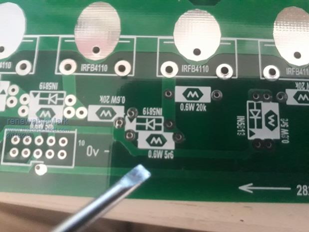 Cheers Caveman Mark Off grid eastern Melb |
||||
renewableMark Guru Joined: 09/12/2017 Location: AustraliaPosts: 1678 |
Hey John, if you could be stuffed could you do a pic or two of the layout you did with the aerosharp cases? Cheers Mark Cheers Caveman Mark Off grid eastern Melb |
||||
Madness Guru Joined: 08/10/2011 Location: AustraliaPosts: 2498 |
Here is mine, photo is a bit blurry though. I turned it 90 degrees to let the hot air rise. 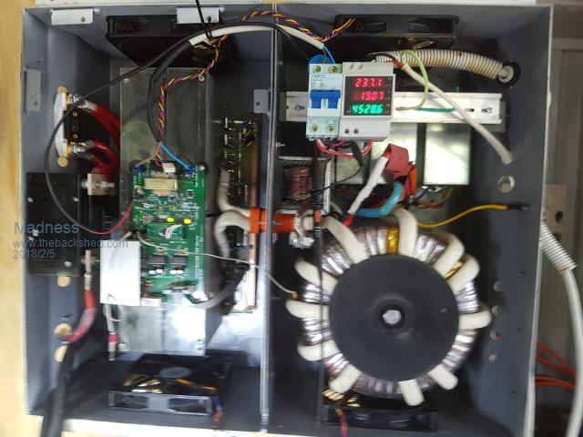 There are only 10 types of people in the world: those who understand binary, and those who don't. |
||||
| johnmc Senior Member Joined: 21/01/2011 Location: AustraliaPosts: 282 |
Good day Mark Yes I am saying that the gate resistors are 4R7 1/2 watt I am having trouble copying Oztules post Reply #289 on: May 28, 2016, 09:27:06 pm on the Anotherpower forum Yes... you must replace the gate resistors with 4r7 ohms, and use a diode across then for faster turn off..... as in this: Can not paste the image but it is from the EG8010 data sheet Other than this, nothing else need change. If you don't change these, it will get very hot very quickly. ..............oztules Here a 3 pictures of my inverter case I needed to add extra depth to the bottom inspire case to fit the large transformer For ease of working on,the next Inverter I will probably build a housing case, similar to the housing, such as made by thebackshed member Tinker 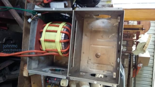 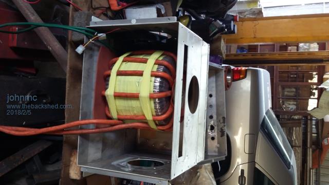 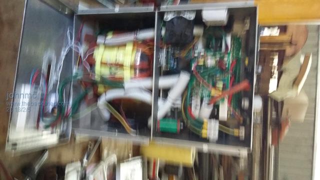 sorry for the image quality cheers john johnmc |
||||
renewableMark Guru Joined: 09/12/2017 Location: AustraliaPosts: 1678 |
Thanks John, what is the reference to the diode? Is it just the resistor that needs changing? Cheers Mark Cheers Caveman Mark Off grid eastern Melb |
||||
Madness Guru Joined: 08/10/2011 Location: AustraliaPosts: 2498 |
Here is the link you are referring to, I found it. Don't know why you are having trouble with posting it. What does Clockman say about these resistors, I have been using 5r6 without an issue. I am sure your problem is elsewhere, are you not able to take photos of your CRO screen? There are only 10 types of people in the world: those who understand binary, and those who don't. |
||||
oztules Guru Joined: 26/07/2007 Location: AustraliaPosts: 1686 |
5r6 if just fine. That is not the problem.. don't know for sure what is, but it is not that. It may be too low a voltage on the gate, For 12v you will have to decrease the resistance on the 120r, and may be best to check gate voltage, as I am suspicious that you are in the 8v range, and they are not turning on properly The diode is there to discharge the gate charge on turn off. It is as important to turn the fet off quickly, as it is to turn it on quickly, the diode helps in this, as it does not rely on the resistor to discharge the gate. I have no idea how the 12v version runs, but if the fets are not turning on fully, then there is your problem. You may need a booster for 12v systems for the gate voltages.... I had not considerd this, and you may have to come straight through ( no regulator for the 12v tip35) just to get up to 12v Edit... not sure why I thought you were running 12v... so you can ignore reference to that.. maybe some one else is, and they may benefit from the comment. ......oztules Village idiot...or... just another hack out of his depth |
||||
| johnmc Senior Member Joined: 21/01/2011 Location: AustraliaPosts: 282 |
Good day all I have rebuilt both the powerboard and the control board with no improvement to the amount of standing power 50 volts and a draw of 2.5 amps the 120 resistor on the control board will get very hot ,does this suggest that the FET gates, there is 24 HY4008 FETs to drive, are they drawing to much current, the transformer makes virtually no noise but produces the following wave form 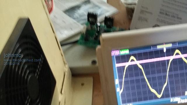 The interesting part is the shape of the wave form as it builds is a sine wave shape 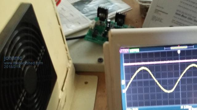 also the first wave form looks as if a triangle shape had been added to the peak of the sign wave . I also removed the inline 4 turn inductor /choke this only increased the standing current to 7 amps,this made no difference to the wave shape There is no 4.7 poly cap (end blown out again) and no large capacitors on the powerboard At the moment I am lost any suggestion will help. Cheers john johnmc |
||||
Madness Guru Joined: 08/10/2011 Location: AustraliaPosts: 2498 |
What is different between the top and bottom sinewave? The 120R resistor does run warm as it is dropping the voltage from 48 down to near 12V. What voltage is the 4.7 cap or is it a bad batch? I have not seen one fail. First picture is what I would expect to see with a resistor in series, the second one looks normal. There are only 10 types of people in the world: those who understand binary, and those who don't. |
||||
renewableMark Guru Joined: 09/12/2017 Location: AustraliaPosts: 1678 |
Nasty!! That's an ass bang!! Did you test the fets? This is the method Mad gave me Mad quote, "I use my 48V battery bank but you don't have that ATM. You could use a 12V battery, I made up a tester before using a hard drive connector off an old computer power supply to stick the FETs in. I use 2 of the big 33 ohm resistors off the Aeosharp PCBs in parallel looking at the fet from the front you have gate, drain and source in that order left to right. So you need +12 (never 48V) to the gate to turn it on, the drain is connected to to the resistor and resistor is connected to positive power. Source is connected directly to ground. It is far easier if you have meter leads with small alligator clips and you must connect as close as possible to the body of the MOSFET (ie less than 1MM away), connect one to middle leg (drain) and the other to the source (right side) when power is applied to the MOSFET with all these connections we want to measure the voltage across these pins. You will need to measure the current at least once also then you can use Ohms law to calculate the RDS ON (resistance Drain-Source while turned on) For HY4008's it should be 2.7 milliohms which is a very tiny amount and why the cheap little testers can't measure it properly. Sometimes you will get a higher reading, disconnect and reconnect the MOSFET as it needs really good contact, if you got them from the same supplier I did they have always been on spec or better, but if you get any FETs that are 10% or more higher (lower volts is better) than the others put them aside and don't use them for the Inverter, they would fine in the fan controller." End quote. Cheers Caveman Mark Off grid eastern Melb |
||||
Madness Guru Joined: 08/10/2011 Location: AustraliaPosts: 2498 |
With no caps and running through a resistor, you don't get a perfect wave form. The reason for running like this to check if you get close to it being correct, if something is wrong it looks a whole lot worse than that. I think it is actually close to being right but I have not been given a much information to work with. There are only 10 types of people in the world: those who understand binary, and those who don't. |
||||
| johnmc Senior Member Joined: 21/01/2011 Location: AustraliaPosts: 282 |
Good day Madness and renewable, The good sine wave is produced just as the transformer is building up voltage The peaked sine wave is when the transformer is at voltage. The 4.7 poly is rated at 400v Will adding a large 10000uf capacitor change the wave shape Madness "First picture is what I would expect to see with a resistor in series" Is that a series load on the inverter? The Fet have a RDS turned on resistance between 2.6 mohms and 2.9 mohms with the vast majority at 2.7mohms. I will try a new power board tomorrow with the only 4 Fets john johnmc |
||||
| Page 1 of 11 |
|||||