|

|
Forum Index : Electronics : Toroid saturation curve?
| Author | Message | ||||
| Tinker Guru Joined: 07/11/2007 Location: AustraliaPosts: 1904 |
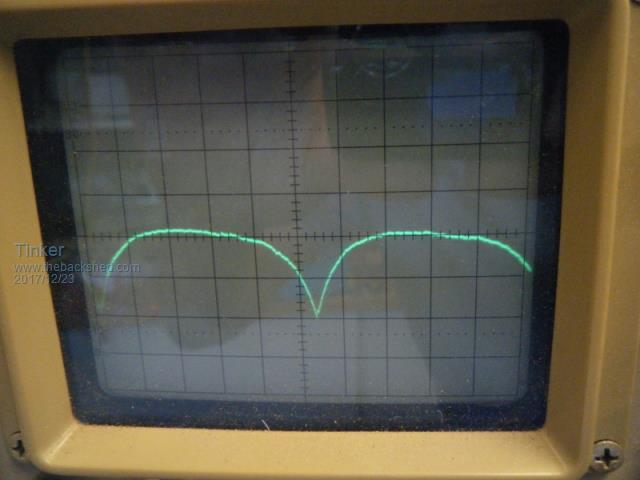
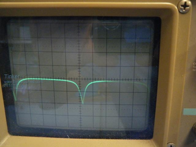
I have another of these 3KW Aerosharp toroids and decided to rewind it for yet another inverter  . .Anyway, having removed the outer 250V winding and the electrostatic shield under that, I was left with the original 230V winding. Wound 3 in hand of 1.8mm dia wire looked good enough to leave it, but add a few more turns. A ten turn test winding gave 11.8V with exactly 230V in with my variac. That calculates to 195 turns on the 230V winding, might add another 30 to that. But first I was going to see when that original 230V winding saturates the core. The you beaut inductor saturation tester that warpspeed described was handy and hooked up. The result is nothing like I expected from observing the traces my inverter chokes produced. This is with 10A peak current, as measured with my hall effect device:  I then wound it up to 50A peak, with the core growling happily:  For the 10A test the input voltage was 40V and for the 50A it was 50V. Lower test currents just lowered the flat bit on top, the dips stayed the same shape. I did not dare to push for higher currents as the 50V already stressed my big tank capacitor (rated 40V). Is that what I should expect or am I doing something wrong? I am just curious when this core saturates with the original winding and what effect another 30 turns would have But I need to know if and where on that curve saturation occurs? Thanks for your suggestions. Klaus |
||||
| Warpspeed Guru Joined: 09/08/2007 Location: AustraliaPosts: 4406 |
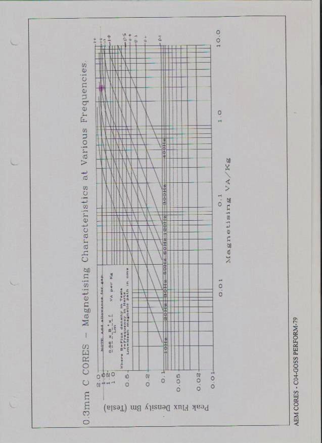
Hi Klaus, Testing these is somewhat difficult because of the very high permiability and lack of an air gap. Its really an ac inductor not a dc choke. If its driven to saturation and the current is then switched off, the remnant flux in the core does not fall back to zero. It remains magnetized permanantly and at a fairly high level. If you again try to drive it to saturation in the same direction it takes remarkably little current to again saturate it. If you want to see the saturation curve, it would need to be fed with a square wave voltage that was ac, or alternated in opposite directions. So a very different type of tester would be required. Anyhow, here is the magnetization curve for 0.3mm grain oriented silicon steel strip, which is what our toroids are wound from. Its a bit difficult to see, but what we should be looking at is only the 50 Hz curve. The vertical axis is the flux density, and the horizontal axis is the magnetizing power, shown as Va's per Kg of core material.  You will see a pink fuzzy dot on the 50Hz curve, at 1.5 Teslas which is where many commercial transformers are designed to run. Notice at higher flux densities the curve goes horizontal. The magnetizing current rises to infinity as the flux goes much higher, indicating complete saturation. If we drop back to lower flux densities say around one Tesla we reach about 1Va per Kg of magnetizing power, and we are into the linear part of the 50Hz curve. If you use the following flux calculator: https://www.electricaltechnology.org/2014/02/maximum-flux-density-bmax-calculator.html Apply that to the above curve, and with care you can estimate the no load idling power of a prospective toroid design. If you actually have a wound toriod in your hands, it can be connected up to a variac and the current into the 230v winding measured at various voltages. It will be HIGHLY non linear. At each step of rising voltage, the current will increase faster and faster as you get closer to saturation. Likewise a small decrease in voltage will give a correspondingly greater reduction in transformer idling power (no load losses). As a rough guide, 1 Tesla might give a core loss of 1Va per Kg of core material. 1.5 Teslas it goes up to something like 3Va per Kg. 1.7 Teslas it goes totally nuts at maybe 10 Va per Kg. I have not been able to find these curves on the internet. All I have is a fairly faint hard to read copy from the AEM catalogue. Cheers, Tony. |
||||
| Tinker Guru Joined: 07/11/2007 Location: AustraliaPosts: 1904 |
Thanks Tony. I now remember plotting that voltage/ idle current relationship when I wound my double stack toroid. I did not have that DC choke tester back then and thought it may work, thanks for explaining why it does not on an AC toroid winding. Just finished adding 30 turns (3 in hand) to the original 230V winding. When it is all tidied up I'll do another voltage/ idle current plot and see where on the curve it is, hopefully not the steep part. Klaus |
||||
| Warpspeed Guru Joined: 09/08/2007 Location: AustraliaPosts: 4406 |
Klaus, I does not take many extra turns to make significant improvements in idling power. The non linearity effect working strongly in our favor. Grid tie inverters do not spend many hours running at no load in the same way battery powered inverters usually do at night. So grid tie transformers are often not especially efficient in regards to idling power, they have no real need to be. Adding extra turns is a great way to remedy that problem. When you have made your measurements, it might be interesting to work out the flux density and the magnetizing Va per Kg from the above curve. The figures should come very close. If you can master that technique, then its possible to make predictions about idling power with as yet untried combinations. Cheers, Tony. |
||||
| Tinker Guru Joined: 07/11/2007 Location: AustraliaPosts: 1904 |
Thanks Tony, I'm more of a trial & error guy, lacking confidence with maths made me do things this way  . .Anyway, I was in for a pleasant surprise when I plotted the idle current/ Volt curve. Very flat this one, with the extra 30 turns, especially when compared to the dual stack curve which turned out 5 times steeper. I wish now I had put on more secondary turns to that dual stack core back then... Some figures: Secondary winding at 230V from variac takes just 45mA. Around that voltage the change is close to 1mA per 5V change. 200V=38mA 220V=42mA 240V=48mA 270V=65mA The variac would no go higher than 270 but I think I'm well into the linear range. For the benefit of anybody about to re wind a similar toroid (190x100x70mm, ex Aerosharp 3KW): I added 30 turns (3 in hand) to the original 195 turn 3 in hand winding. Inner winding, white & black leads. Adding these turns is a lot quicker than rewinding the lot, as I did with my first two conversions.They fit neatly in one layer all around, with room for a dividing string between the 3 in hand turns. I also replaced the copper foil static screen winding and with everything wrapped in mylar tape, ready for the primary winding, the center hole is still 70mm diameter. That should easily fit 25 or 26 turns (not sure yet which) of my 3.2x5mm enamelled copper, 4 in hand. Using insulated welding cable would be a bit tougher to fit that sq mm area size. Klaus |
||||
| Warpspeed Guru Joined: 09/08/2007 Location: AustraliaPosts: 4406 |
Excellent result there Klaus. At 230v that is probably about 45mA or 10.35 Va of idling power. Pretty low for a thing that size. Cheers, Tony. |
||||