|

|
Forum Index : Electronics : Power Supply Upgrade.
| Author | Message | ||||
| Tinker Guru Joined: 07/11/2007 Location: AustraliaPosts: 1904 |
I had built that power supply original article some time ago but only now found time to test it. Well, I might need some ideas here, that thing is driving me bonkers. It worked initially as expected but when I connected my you beaut Chinese dual Volt/Amp display I got some wires wrong and the display died. So, after waiting weeks for a new display I put everything together again and the new meter works but the power supply is odd. It worked, volts from 0 to 30 and Amps as expected but a lot of hash on the output. Fitted a .1uF ceramic to the terminals and the hash almost went away. While trying to get rid of all of it (hash) the supply died  . .Now it comes on at 28V and can be adjusted to 30V (no current!), that's it. I'm chasing my tail trying to figure out what is wrong with it and am fishing for ideas here. Some symptoms: The -5.1V rail was always odd, it seems to change with different output voltage settings, like it gets loaded somehow. The reference sits at 10.00V. The 1k resistor to the base of the driver transistor (D882) gets very hot, it actually took out the 9014 transistor (b to e short). The current IC output (pin6) suits at + rail voltage. Unloaded rail voltage is 33VDC. I have been swapping parts around all day and getting nowhere... I even fitted a trimpot in place of the 1K5 resistor at the base of the 9014 transistor to change the shutdown trip but that does not fix it. Klaus |
||||
| Warpspeed Guru Joined: 09/08/2007 Location: AustraliaPosts: 4406 |
Klaus, I have now built five of these, without any serious problems. I did have one of the 100k multiturn pots come with an open circuit wiper, something I have never seen before. And the zeners are not branded and have nothing printed on them which makes me suspicious, as the final voltages they produced turned out to be a bit odd. But otherwise its been all smiles here. It sounds like you have a serious problem with the D882, or even the D1047. There should be massive total current gain there if both are working, and the 1k resistor in the base of the D882 should be doing hardly anything at all. A BD140 works fine in place of the D882 and will be much easier to source from either Jaycar or Altronics. Likewise try a mosfet replacement for the D1047, at least as a temporary measure. If you go for a mosfet output, replace the diode in the base of the D882 with a suitable zener. That will prevent a possible 30v from finding its way to the mosfet gate under some extremes of operation. Hash sounds like something going leaky or breaking down. That might also explain the loading on the -5v supply. If replacing both transistors does not fix the hash, try swapping the op amps around. If you don't have any spare TL081's the LF356 is a direct plug in equivalent. One thing that makes me a bit nervous is the maximum supply voltage ratings of the op amps. They are running right up at the maximum limit, and possibly beyond. One of yours may be breaking down creating some hash without actually failing totally. Cheers, Tony. |
||||
| Tinker Guru Joined: 07/11/2007 Location: AustraliaPosts: 1904 |
Thanks Tony, yes, it has something to do with the main transistors. You are lucky to have got 5 going with no problems, that circuit is a bit tricky to trouble shoot. A BD140 will not work, I'm sure you meant BD139 (NPN?) The D882 measured very odd when I took it out and tested the junctions, so its now discarded. I tried various main transistors, even a HY4008 mosfet but no luck yet. The original article used a 3055 transistor, I have a TIP3055 in a suitable case that fits so I just need to get a BD139 or two. Tried BD135 and a few similar NPN's I had in my parts box, no success, somehow these two transistors need to like one another to work IMO. I am wondering how your mosfet idea works, I thought these things are either fully on or off which would not work for variable output voltages. Lack of knowledge on my part here. I did order 10 TL081's so I got a few to play with. Jaycar sells the TL 071 which is quite similar, I got three of these also before the others arrived from ebay. You are right, that circuit runs at the limit of the 36V amplifier ratings, what is the exact voltage of your positive rail? I power it now through my variac to get exactly 30V there now but the last tests before I gave up for the day produced the opposite of before, only 0-2V output. I think once I have the right combination of driver transistors I might pass the winning post... Klaus |
||||
| Warpspeed Guru Joined: 09/08/2007 Location: AustraliaPosts: 4406 |
Yes you are quite right its a BD139 NPN. I always get confused about that, I have a sort of mental block that I can never remember which is which, and seem to always get it wrong. No matter how many times I use that family of devices I always get confused and need to look up the data to be sure which gender it is. That circuit can be a bit tricky, which is why I took the trouble to trace it all out very early on to remove most of the mystery. Mosfets do have a very short linear region, and massive gain at that point. They make excellent source followers for a linear dc power supply, and have the really big advantage that the current through the mosfet spreads evenly through the device. Any area that runs a bit unevenly hot on the silicon die of a mosfet increases in resistance locally, so the current to some extent then avoids the hot spot. The result is very stable thermal operation when there is both a high voltage and a very high current combined and high power dissipation in the device. Bipolar transistors are the exact opposite. Any hot spot conducts more readily, so the current crowds the hot spot. That makes it even hotter. So what you get is a thermal instability where an area starts to run a bit warmer, the heat quickly concentrates and the hot spot shrinks in size and spikes up in temperature until the silicon actually melts in an incredibly small area. The device then dead shorts. Cheers, Tony. |
||||
| Tinker Guru Joined: 07/11/2007 Location: AustraliaPosts: 1904 |
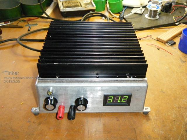
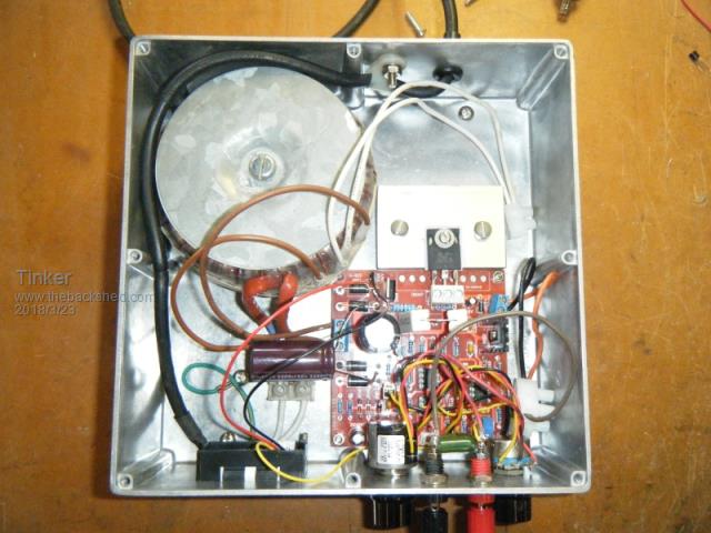
Found the problem at last, it sure gave me the run around. It was the R47/5W resistor going open circuit for no reason at all bar bad manufacturing. I never before came across a 5W resistor going open without getting stinking hot beforehand. This one showed no signs of heat stress at all. It must have been on/off initially for the supply to work sometimes, thankfully it got o/c permanently so I could track it down. Now the supply works fine, 50W is the most I get out of it (25V/2A) with a clean wave form. More load and the saw teeth start appearing, I already have doubled the main capacitor but think they should have left room to fit a 10000uF cap at least. Noise is very low (<10mV) at the output up to that 50W load. It did require to fit a 0.47uF greencap across the output terminals for that, without that cap there is lots of noise. The pics below show the finished power supply, the voltage at the meter is the max. unloaded. This drops to around 27V flat out loaded.  And a pic of the inside:  Klaus |
||||
| Warpspeed Guru Joined: 09/08/2007 Location: AustraliaPosts: 4406 |
Very impressive Klaus, yours is a lot simpler mechanically than the way I have constructed mine. Thermally it is very well thought out and it looks very efficient. I think we have both been a bit unlucky with receiving faulty components in our kits, its really disappointing to correctly assemble a kit and then have it not work first attempt, especially when there is no circuit diagram to work from. In my case it did actually work, but the potentiometer in the first one I assembled did not appear to do anything at all, which seemed a bit strange. And without a circuit, I had no idea what that potentiometer was supposed to do. The second kit I assembled worked perfectly. But if I had only bought the one kit, I would probably never have found that particular fault. I tested my three other boards with clip leads, and they all work fine. Those kits are excellent value, and work pretty well just as they are, but it does have its limitations when working up near 30v. It might have been better calling it a 25v maximum supply not a 30v maximum supply, and limiting the output voltage to just 25v. I now use both of my supplies all the time, and am pretty happy with them. Still need to get plastic boxes to finish off the last three, I now have all the other parts. Thats a hundred dollars worth of plastic boxes, so I will probably get them one at a time as I have already done with the three transformers. Cheers, Tony. |
||||
| disco4now Guru Joined: 18/12/2014 Location: AustraliaPosts: 897 |
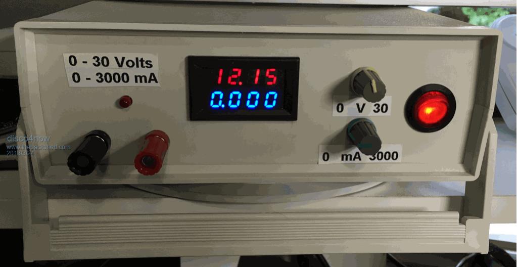
I built one from the Banggood kit. $6.00 at the time. Price seems to go down sometimes in you look at it more than once. Was $11.00 then after looking again was down to $8.00.  I used this case which is about $14.00 now. I used this case The Banggood item has a link to a manual which includes a circuit that matched the kit. Bangood Kit Bangood Manual I also used their meter and heat sink. Regards Gerry Latest F4 Latest H7 |
||||
| Warpspeed Guru Joined: 09/08/2007 Location: AustraliaPosts: 4406 |
What amazes me Gerry, is that they can supply a top quality circuit board, plus all the components at such a low price, AND still make enough profit to make it worthwhile. Cheers, Tony. |
||||
| Tinker Guru Joined: 07/11/2007 Location: AustraliaPosts: 1904 |
Thank you Gerry, I wish I had that manual information to begin with... The kit being now so cheap I just ordered a spare one  . .I'm curious, can you get the full 3 Amps from your supply? Mine peaks out at 2.5A, I played around with various resistors to load it. The transformer is rated 150Va, should be big enough. PS, I tried these V & A combined displays, blew both of them up while trying to find that odd fault above. But I found the digits are far too close to to the display screen edge to be able to read them without tilting the whole supply box up. So I now use a Volt only display, very easy to read. Klaus |
||||
| Warpspeed Guru Joined: 09/08/2007 Location: AustraliaPosts: 4406 |
Klaus, I noticed that component spreads can make quite a big difference to how high either the voltage or the current can be set when each is tweaked up to full maximum. One 5.1v zener controls the +10.2v reference which is fairly important, the other the minus five volt rail not so much. One of my zeners ended up producing just over over 5.6v and a couple ended up being less than 5.1v. These unmarked and unbranded zeners are junk. They are probably quite stable (?) but the initial voltages are all over the place. I tested all mine and picked the closest ones for the 10.2v reference. Those 4R7 5 watt resistors are not going to be wonderfully accurate pieces either. And even the total resistance of those small carbon potentiometers can be a bit dicey. It all adds up... Cheers, Tony. |
||||
| Tinker Guru Joined: 07/11/2007 Location: AustraliaPosts: 1904 |
Thanks for that info Tony. I did a little more testing today. The Ac secondary of my transformer easily does 5A @ 24V by itself. I then swapped my TIP3055 main transistor for the original NPN as supplied with the kit. This improved things, I can now get 3A @ 24V DC out of the thing, probably leave it at that. At less load it goes up to 30.7V DC output. The original driver transistor had blown so I'm using a BD139 there. I tried several other NPN's from my parts box but that one worked best. The reference voltage is very close to 10.2V as is the negative rail to 5.1V. The latter is stable now since I replaced the faulty series resistor - I use 2 x R22/5W in series, have not measured their exact combined resistance. These do not get super hot but that 2K2/2W resistor across the main capacitor does - wish I had spaced it off higher from the PCB. When that new kit arrives I might do some more testing to see how far I can tweak this project. That 100K trim pot, BTW, does not do anything. Can't be bothered to replace it as the Volt pot does adjust down to 0.00V. I'm using a 10 turn there, nice to set accurate output. Klaus |
||||
| Warpspeed Guru Joined: 09/08/2007 Location: AustraliaPosts: 4406 |
I too have plenty of grunt coming from my transformer. 34.4v dc no load, and 31.3v dc at three amps load, but with rather a lot of ripple. Agree that a much larger reservoir capacitor than that supplied in the kit would be a big step forward. The 3055 is an ancient device with rather low current gain, especially at high output current. The D1047 is a much better transistor in every respect, but its right on the edge of thermal runaway and, is likely to suddenly fail without warning if it ever gets really hot. If it does fail, it will die shorted and could easily then fry whatever is connected to the output with the full 30v. One of my supplies tops out at 2.8 amps, the other at 3.0 amps under short circuit. Current regulation is excellent up to about 15v output, where the above full max output current can still be reached. Things are not so good with a ten ohm load. I can only reach 20v and 2.0 amps. The mosfet modification has made that particular problem worse, but it will have improved the robustness and reliability which for me is a worthwhile tradeoff. I rather expected something like that, which is why I am building five of these supplies. I can always connect two or more supplies in series or parallel to do any really big jobs if that need ever arises. The reduced output voltage disadvantage with using a mosfet output device could be fixed by being able to drive the gate up considerably higher than the main 30v dc supply rail. I spent a long time looking for a suitable high voltage op amp to replace the TL081, something in an 8 pin dip that would plug straight in. There is not much available out there that will do that. I eventually discovered the Burr Brown OPA445-AP. This has better specifications than the TL081, especially operation up to +90v ! http://www.alldatasheet.com/datasheet-pdf/pdf/56772/BURR-BROWN/OPA445.html I now have some of these and tried one in the original circuit, and it worked perfectly, but have not gone any further with that. A voltage pump circuit and zener regulator (similar to the -5v circuit) could supply about +40v to +45v (at just a few milliamps) for a high voltage op amp that can properly drive the output mosfet to turn it on fully. The mosfet gate wold require a zener to safely limit the maximum gate voltage, but that can easily be done by replacing the existing 1N4148 with an appropriate zener. The full dc output from the rectifier should then be available at the power supply output without any excessive voltage drops through the regulator. But it would require modifications to the circuit board that I would rather not do. A simpler (but more expensive) solution might be to just fit three of those OPA445 op amps and jack up the main incoming dc rail with a 30v transformer instead of a 24v transformer and fit a big zener protected mosfet. That would increase the power dissipation, but it would be the simplest way to fix all of the limitations in one hit without needing to cut any tracks on the circuit board or physically change the circuit board from the original. It would just be a case of fitting different components to the same holes. Cheers, Tony. |
||||