|

|
Forum Index : Electronics : designing ATS ?
| Author | Message | ||||
| brac321 Regular Member Joined: 30/11/2016 Location: SloveniaPosts: 54 |
Playing with own idea on how to design ATS (Automatic Transfer Switch) - device for safe fully automatic switching between two completely non synchronized power sources (PV and Grid), with priority input, wired on to Inverter that uses soft start, also watching on to too low and too high input voltages, plus taking care for safe transition in any direction and from any state ... I know, there is plenty of mechanical ones on the market. Unfortunately they do not meet all my needs. So I "put together" my own toy. For now, on the table it operates flawlessly - testing with tiny 25A contactors. Now waiting on to 63A ones to arrive ... Note: left two breakers were used only to simulate both power sources. And next one (Green) is used to manually force ATS to switch between sources. OffGrid 24/7: 250w black mono solar panels 6.4kWp, 1x Midnite Classic 150, 1x MorningStar MPPT 60, battery bank 840 Ah @ 48v, modified LF-8K inverter, DC/DC, hot water harvesting, etc. |
||||
| brac321 Regular Member Joined: 30/11/2016 Location: SloveniaPosts: 54 |
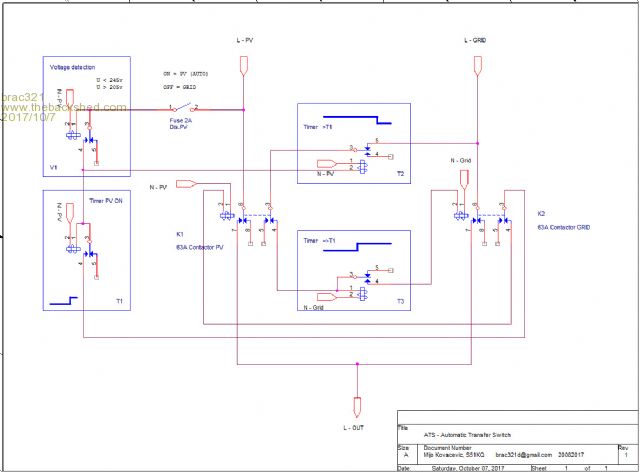
ATS is now for days on the wall and operates flawlessly. It was designed to automatically switch complete home appliances between non synchronized PV (Off Grid inverter) and city Grid, with PV priority, that can be disabled by 2A breaker. We use/share common N (neutral) in our system, thus only L (live) is switched thru ATS. Anyhow, N can be too simply by replacing both Contactors (K1 and K2) with the larger ones. Voltage detection unit in front shall prevent transfer to PV source under out of range conditions, plus it takes care about PV inverters Soft start. There were 3 Timers used. T1 as delay for PV source, T2 is needed to block GRID detection during T1 activities, therefore it must be set to a longer time as T1. Timer T3 is delay needed for GRID source. ATS will operate independently of power presence on its inputs. Here is my schematic if someone interested ...  OffGrid 24/7: 250w black mono solar panels 6.4kWp, 1x Midnite Classic 150, 1x MorningStar MPPT 60, battery bank 840 Ah @ 48v, modified LF-8K inverter, DC/DC, hot water harvesting, etc. |
||||
| Solar Mike Guru Joined: 08/02/2015 Location: New ZealandPosts: 1138 |
Cool, can you provide links to where you purchased the components. As it stands would not meet code here in NZ as neutral is considered a live conductor and must be switched along with the line. Cheers Mike |
||||
| brac321 Regular Member Joined: 30/11/2016 Location: SloveniaPosts: 54 |
No problem Mike, will modify sch a bit to include neutral lines and links to the components used. OffGrid 24/7: 250w black mono solar panels 6.4kWp, 1x Midnite Classic 150, 1x MorningStar MPPT 60, battery bank 840 Ah @ 48v, modified LF-8K inverter, DC/DC, hot water harvesting, etc. |
||||
| brac321 Regular Member Joined: 30/11/2016 Location: SloveniaPosts: 54 |
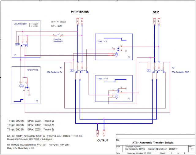
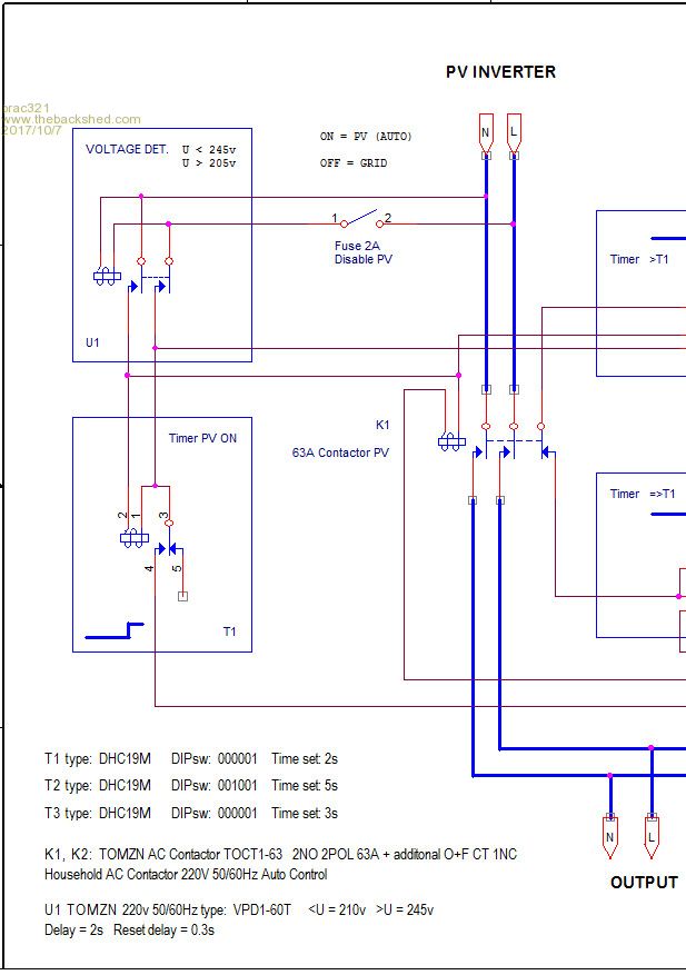
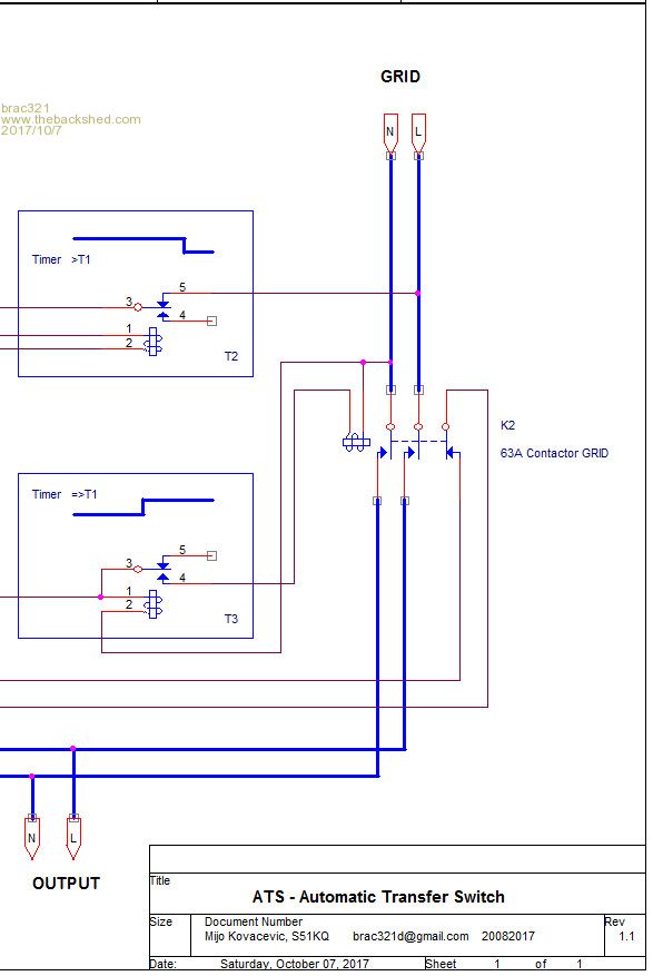
ATS S51KQ, parts: 1x 2A DIN rail breaker 1x Over and under voltage protection relay VPD1-60T Settings U1 TOMZN 220v 50/60Hz VPD1-60T: <U = 210v (205v) >U = 245v Delay = 2s Reset delay = 0.3s 3x Multifunction Timer Relay AC 240V DHC19M Timer settings: T1 type: DHC19M DIPsw: 000001 Time set: 2s T2 type: DHC19M DIPsw: 001001 Time set: 5s T3 type: DHC19M DIPsw: 000001 Time set: 3s 2x AC contactors 2NO + 1NC 63A or amperage depending on your needs one can use TOMZN TOCT1-63 plus O+F CT 1NO 1NC for 1NC contact, or any other contactor with 2NO + 1NC signaling contacts All signaling wires can be 0.25 - 0.5mm2, except the thicker power lines (L,N). These are 4 or 6mm2! Below is sch for switching L+N from both sources. If you need normal size JPG schematic, send me your email...  Left side of sch  Right side...  OffGrid 24/7: 250w black mono solar panels 6.4kWp, 1x Midnite Classic 150, 1x MorningStar MPPT 60, battery bank 840 Ah @ 48v, modified LF-8K inverter, DC/DC, hot water harvesting, etc. |
||||
| yahoo2 Guru Joined: 05/04/2011 Location: AustraliaPosts: 1166 |
I have been looking at the article in the May2018 Silicon chip about building a UPS. The approach to the transfer switch using the arduino IDE and a relay driver to control three relays looks sound at first glance. I guess I will wait for part 2 to see the detail. I always worry about the possibility of 700 volts of potential frying stuff if things are not sequenced right. it looks like it could be relatively inexpensive to build, that has perked my interest. To be able to isolate an off grid inverter and transfer the connected GTI between the grid and remote system based on rules and inputs from other places is like the holy grail to me. The home automation stuff I have been fiddling with can access data and parameters from pretty much anywhere and sort it with logic but the missing piece has been doing something useful....and practical with it. A controllable transfer switch would enable some really neat features. I'm confused, no wait... maybe I'm not... |
||||