| Author |
Message |
karmacoma
Newbie

Joined: 25/08/2015
Location: AustraliaPosts: 17 |
| Posted: 06:45pm 13 Feb 2017 |
 Copy link to clipboard Copy link to clipboard |
 Print this post |
|
I have been using two identical 12" desk fans in the tropics, powered by 15V DC brushless permanent magnet motors. The controller on one of them has failed.
I had them running on my little 12 Volt PV system (100W panel, mppt regulator, 40Ah battery, a few 2W lights, and the fans).
So, I got the controller board off the failed one, and double-checked it against the still-working fan (test 1: swapped out the board, test 2: swapped out the motor) -- definitely it's something on the board that's kaput. It's basically a rotary switched potentiometer feeding to an LM317 regulator. But I don't understand the circuit, and I don't know how to diagnose which component has failed. I have drawn out a circuit diagram and took some photos (see below).
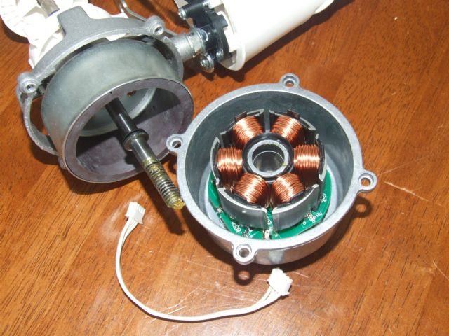
1) I Googled LM317 fan controller circuits, but mine doesn't look like any of them -- so how does this one work? And why does the motor have three inputs??
2) How would I test components on the circuit board to isolate the dead component (no oscilloscope here, only a multimeter)?
3) thinking laterally, maybe I should just do away with the speed control, and route the supply voltage more or less directly to the motor. While the speed control is handy, I read somewhere that turning the speed down slow will result in higher current use and heat from the LM317. So just running full speed only might be better. But I don't know what that third wire into the motor does, or how I would need to deal with it if I just route the motor input directly from the PV storage battery.
Any help greatly appreciated!
- Ian -
Here is the circuit diagram and some pics:
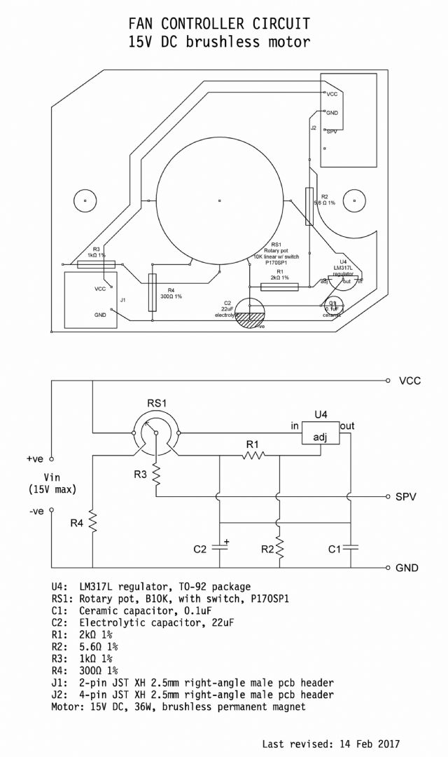
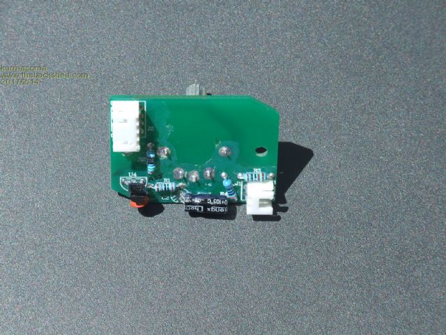
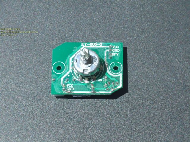
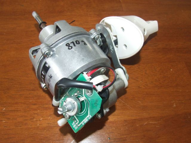
[Fan specs:- OEM: Genios Development Co., Taiwan. Brand: Matric. Model: Macaron 30cm DC Fan. Model nr: MG-DF1202. Manufactured 06/2014. 15V DC, 36 watts, brushless permanent magnet motor.]
|
| |
VK2MCT
Senior Member

Joined: 30/03/2012
Location: AustraliaPosts: 120 |
| Posted: 02:54pm 14 Feb 2017 |
 Copy link to clipboard Copy link to clipboard |
 Print this post |
|
Just some thoughts:
The motor has power VCC and GND.
SPV is probably speed control of the motor.
There is a circuit board behind the wire coils of the motor. I expect there is complex electronics on this to power the coils in the correct order and power to get the motor to spin.
Faultfinding:
With power applied and pot 'ON'.
Please report the voltage between:
U4 IN and GND
U4 OUT and GND
VCC (to motor) and GND
John
VK2MCT |
| |
joebog1
Senior Member

Joined: 07/11/2015
Location: AustraliaPosts: 114 |
| Posted: 03:44pm 14 Feb 2017 |
 Copy link to clipboard Copy link to clipboard |
 Print this post |
|
I think John ( VK2MotorCircuiT  ) has an idea. ) has an idea.
The terminal SPV would have to have extra components involved, because for the life of me it doesnt really make sense.
The pot is a standard one!! it uses the metal case as a conductor, and maybe as a screen to prevent RFI ( Radio Frequency Interference) The pot is worth about 2 bucks.
The LM317 is "almost" cookproof so I doubt thats it.
BUT a pot thats gone open circuit could cause the problem.
Its easy enough to measure:
There are 3 legs on the pot:
arranged quite close together.
measure between the two outermost legs (NOT the ones that hold the pot to the PCB )
It should measure about 10K ( give or take, its probably plus/minus 20% )
NEST : measure between the centre leg and either of the outside legs, and that should vary as the pot shaft is rotated.
NEXT : moving your multimeter probe connected to the outside leg of the pot, to the OTHER outside leg of the pot, re measure and it should also change when the shaft is rotated. IF the meter shows that the reading jumps all over the place, OR doesnt read at all, its the pot.
Joe |
| |
karmacoma
Newbie

Joined: 25/08/2015
Location: AustraliaPosts: 17 |
| Posted: 06:02pm 14 Feb 2017 |
 Copy link to clipboard Copy link to clipboard |
 Print this post |
|
Thanks so much for your help, John and Joe!
Starting with the pot first (and a new battery in the multimeter)
1) Resistance across the ends of the carbon track
(i.e. the two outside legs of the trio): 4.3 kΩ
(for comparison, the pot in the working unit is also 4.3 kΩ -
that's less than the spec 10 kΩ for some reason).
2) Resistance between carbon track and wiper when shaft rotated
(i.e. middle leg to either outside leg of trio): varies 5Ω to 4.6kΩ
3) Same as 2, but middle to other outside leg - same result.
Pot seems to be working, but resistance is half of the rated 10K.
(on the working unit, could this be why the fan power consumption is only 10W 'flat out', instead of the rated 36W?)
VOLTAGES
--------
A). **NON-working unit** Power ON, Pot ON, (15V DC power)
4) U4 IN to GND: 50 mV
5) U4 OUT to GND: 1 mV
6) VCC to GND: 15.01 V
B). Working unit (for comparison), power on, pot on:
U4 IN to GND: 15.00 V
U4 OUT to GND: 5.06 V
VCC to GND: 15.00 V
SPV to GND: <1 V min to 4.90 V max (as pot is turned lo to hi)
So, what does that mean? A new LM317, or is it something else?
BTW this is very cool, to be fault-finding around a pcb - new for me.
- Ian -
|
| |
VK2MCT
Senior Member

Joined: 30/03/2012
Location: AustraliaPosts: 120 |
| Posted: 06:25pm 14 Feb 2017 |
 Copy link to clipboard Copy link to clipboard |
 Print this post |
|
So:
No significant voltage on the IN of U4 -
probably means there is no significant voltage at the POT SWITCH connection to U4.
Check voltage at either end of the POT SWITCH again to GND.
Again with POT ON of course.
Report Back.
John.
Edited by VK2MCT 2017-02-16 |
| |
karmacoma
Newbie

Joined: 25/08/2015
Location: AustraliaPosts: 17 |
| Posted: 06:50pm 14 Feb 2017 |
 Copy link to clipboard Copy link to clipboard |
 Print this post |
|
Non-working unit:
1) Measuring across terminals of the pot switch = 14.77 V,
and this is the same whether the pot switch is turned on or turned off.
2) Measuring across the outer legs of the carbon track = 1 mV
Working unit, for comparison:
1) across pot switch (switch on) = 2 mV
2) across legs of carbon track = 5.1 V
- Ian -
|
| |
VK2MCT
Senior Member

Joined: 30/03/2012
Location: AustraliaPosts: 120 |
| Posted: 07:15pm 14 Feb 2017 |
 Copy link to clipboard Copy link to clipboard |
 Print this post |
|
Ah ha
Pot switch or it's connection is faulty.
Prob maybe the connections to the switch part of the POT.
Due to flexing/movement of the POT KNOB.
You should be able to use the ohms setting of your meter to 'chase' that there is 'continuity' from the board to the actual connection at the back of the POT. Power OFF for this.
OR
Prob is inside the back of the POT.
Replacement would be hard to obtain I expect.
John |
| |
karmacoma
Newbie

Joined: 25/08/2015
Location: AustraliaPosts: 17 |
| Posted: 07:52pm 14 Feb 2017 |
 Copy link to clipboard Copy link to clipboard |
 Print this post |
|
John, thanks heaps for your advice. And it's been a nice introduction to fault-finding on a pcb for me. Previously I've just looked for smoked or burst components. This is a whole level up!
Something I noticed just now, on the non-working unit there is indeed flex in the upper half of the pot relative to the lower part. The pot on the working unit is much more rigid.
As it happens X-On Electronics in Perth is selling this same type of pot (P170SP1) on eBay. Element14, RS, etc don't do them - I guess they're a bit cheap and nasty.
Ordering now!
Thanks again
- Ian - |
| |

