|

|
Forum Index : Electronics : Inverters - Big Inductor Thing....
| Author | Message | ||||
Grogster Admin Group Joined: 31/12/2012 Location: New ZealandPosts: 9308 |
Hi all.  Where to start with the inductor? Is there an ideal inductance I should be aiming for? I see in all the other threads, people winding up their ones, but no-one talking about what the inductance is or was, and why it needed to be that etc. If anyone has any links to other threads where they talk about this, and how to work out the value of the inductor you need to make, or links to anything else useful in that regard, I would appreciate it much.  Night night for now.  Smoke makes things work. When the smoke gets out, it stops! |
||||
| Solar Mike Guru Joined: 08/02/2015 Location: New ZealandPosts: 1138 |
Guess you need a core to start with that can handle DC without saturating it, I intend to use these Ferrite Core you get three of them for that price, an air gap can be easily added to prevent saturation. Perhaps use flat wire to get the required cross section area and as many turns as will fit. Perhaps others can explain the theory why this core is required.. |
||||
Madness Guru Joined: 08/10/2011 Location: AustraliaPosts: 2498 |
Hi Grogster, I take you are talking about the choke between the Power PCB and the Toroid? I see on another thread here you show the "Big Inductor Thing" in the image below.  Is that the filter in that image or the Ferrite Choke? If it is the choke it goes between the Power PCB and the Torroid primary. If it is meant to be the filter it has inductors in series on both L & N and capacitor across the output. I don't know the values for the filter, I have some Aero Sharp ones I can send you if needed. The choke is 3.5 turns of conductor, as heavy as you can fit conductor into the core, you can get them on Ebay but took forever for the first one I ordered or from RS components and their part numbers are here. 6479351 2 Core ferrite E65/32/27 N27 7200nH 8407308 1 Bobbin E65/32/27 There is no gap, people have tried that and it works best without it and when you get it all right super glue the ferrites together. If you search through Tinkers build you will see some info there. A useful tip is to Google Oztules and the subject you are looking for, ie "Oztules Choke". There are only 10 types of people in the world: those who understand binary, and those who don't. |
||||
Grogster Admin Group Joined: 31/12/2012 Location: New ZealandPosts: 9308 |
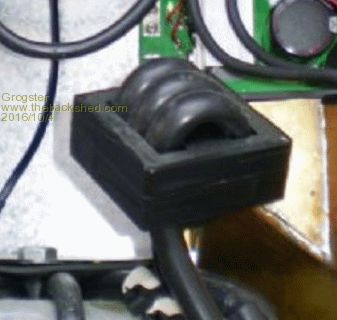
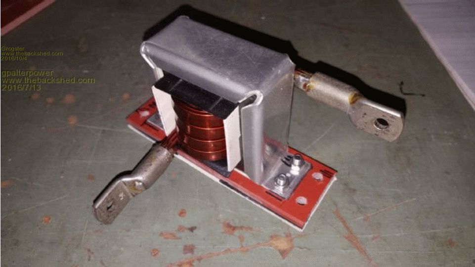
Yeah, I think I have that diagram wrong - the "Big inductor thing" is supposed to be on the PRIMARY. I am talking about these things:   Those images stolen from other threads here. Is it not that mission critical? Just at least three turns inside the ferrite core? I am wanting to know how important this part is to get right, or if it is reasonably forgiving, so long as you have one there of some sort..... Smoke makes things work. When the smoke gets out, it stops! |
||||
Madness Guru Joined: 08/10/2011 Location: AustraliaPosts: 2498 |
Hi Grogster, Yes, correct it goes on the primary. I think I have the history part of this right if I am wrong can someone correct me please. If you look on a site called Energy Matters Oztules was working on improving the Chinese Inverters that the ones we are playing with now evolved from. Those Inverters where using 200W on idle, adding this inductor was the solution to drastically reduce the idle current. I am not sure about how critical the values are, the parts from RS are not prohibitively expensive. I have seen somewhere on a forum where someone salvaged inductors out of some old electronics. There are only 10 types of people in the world: those who understand binary, and those who don't. |
||||
oztules Guru Joined: 26/07/2007 Location: AustraliaPosts: 1686 |
It is a tiny inductance.... too small to have any effect really on the 20khz It is in the region of 12-20 uh.... not critical after about 12uh.. a bit more is better , too much seems to reverse the effects. I don't know why it works so well... it may have something to do with switching losses in the fets, and this small inductance allows the switch to get fully on before the current really gets going... cant see how else it can make a such a huge difference, with such a small inductance. I think it was windspeed that promulgated this theory, and I can't think of anything better. .........oztules Village idiot...or... just another hack out of his depth |
||||
Grogster Admin Group Joined: 31/12/2012 Location: New ZealandPosts: 9308 |
Thanks chaps.  I will work on the 3.5 turns concept then. Seems to be working for everyone else. I wanted to ask, cos sometimes these things can be specific to the transformer you are winding or something. Better to check with those in the know first. I will work on the 3.5 turns concept then. Seems to be working for everyone else. I wanted to ask, cos sometimes these things can be specific to the transformer you are winding or something. Better to check with those in the know first.  Smoke makes things work. When the smoke gets out, it stops! |
||||
| Tinker Guru Joined: 07/11/2007 Location: AustraliaPosts: 1904 |
If you use round cable of a decent size then you are limited to 3 turns and it works well. If you are using rectangular enamelled wire you can fit 3.5 or even 4 turns of 60mm sq area max and it works marginally better. A fair bit of work for a small gain  . .Round cable can be wound on by hand, you'll need to wind rectangular wire on a lathe or such. Buy the cores with the plastic bobbin if you get them from e-bay. Cut the bobbin carefully into a right and left half (see my tread "tinkers inverter build") and you can then wind your coil on a strong dummy center and insert the fragile bobbin halves when the coil is finished and then stick the lot together with epoxy. Klaus |
||||
Grogster Admin Group Joined: 31/12/2012 Location: New ZealandPosts: 9308 |
Awesome - thanks for the pointer - I will have another look at your thread. It will just be wound from the welding cable I am using for the primary. Smoke makes things work. When the smoke gets out, it stops! |
||||
| gpalterpower Senior Member Joined: 19/07/2009 Location: AustraliaPosts: 175 |
Grogster, When I wound mine I found that I could get nearly 4 1/2 turns on the ferrite core. I was thinking that 3 1/2 was optimal, but fitted the extra only because I could to fill the gap and to prevent the turns being too loose. My stand by current is only 0.7 amps on 24 v so im not sure if this is due to the extra turn or not but Im pretty happy with the outcome. Now I dont know either how they work but is amazing that it does and it definitely made a difference. I tried the inverter without it jumped back to 4.5 amps. Eeeeh! Power hungry. On another note I was wondering if the ferrite E core could be replaced by a small torroid, say bout 80mm dia. I have a spare one from a speaker amp setup and am contemplating stripping it down, rewinding with 50mm and giving one a go in my old hungry "power star" inverter as an experiment. I have read the thread from the Energy Mattery forum ...(https://forums.energymatters.com.au/solar-wind-gear/topic3344.html) site but a toroid was fitted firstly in place of the 2 E and I cores before any other changes/additions were made so I guess we'll never know if by just fitting a choke will make any difference to the idle current. When I have a spare weekend ill give it a go. Marcus if it aint broke dont fix it!! |
||||
Grogster Admin Group Joined: 31/12/2012 Location: New ZealandPosts: 9308 |
Cool, let us know what happens, cos winding the choke onto a toroid core would be easier then the IE cores, but whatever works.... In transmitter aerials for FM radio stations(low power ones!), the likes of a J-pole or Slim-Jim use an open-air choke exactly like this to prevent the sheild of the feed coax from radiating signal, as the J-pole or Slim-Jim aerials are effectively a DC short-circuit via the aerial itself and it's matching. They are not a short-circuit at the tuned RF frequency though, but to any normal DC circuit, it would represent a dead short across the cable.  Obviously, the choke here on these inverters is doing something similar like snubbing out back EMF from when the AC cycle switches to the other side of the sine-wave or something - a proper electrical engineer might pop up here and explain it in technical terms for us all to understand!  Smoke makes things work. When the smoke gets out, it stops! |
||||
| Tinker Guru Joined: 07/11/2007 Location: AustraliaPosts: 1904 |
I tried the ferrite ring idea, it gives a much worse standby current than the E core. They use those rings in Latronic inverters at the primary winding. 4 of them stacked and wound with many in hand 2mm wire. I test wound one with 4 turns of 25mm sq cable and, as I said above, it was worse than the E core. Hopefully your results are better. Klaus |
||||
Grogster Admin Group Joined: 31/12/2012 Location: New ZealandPosts: 9308 |
Acknowledged. Back to the EI/EE core idea then. I am still very interested in gp's results though.  Smoke makes things work. When the smoke gets out, it stops! |
||||
| gpalterpower Senior Member Joined: 19/07/2009 Location: AustraliaPosts: 175 |
It could be a while before I have a spare weekend. Most of mine are pretty full at the time being. if it aint broke dont fix it!! |
||||