
|

|
Forum Index : Electronics : Grogster’s Inverter Attempt.....
| Author | Message | ||||
Madness Guru Joined: 08/10/2011 Location: AustraliaPosts: 2498 |
Oztules tells me he has had 2OZ boards running pretty hard with no issues, the voltage drop is only very slight, also you can solder the 3 MM rod onto the PCB. I have just got my build running See here it is on 2 OZ PCB I etched myself, had it running for some time today at 2400W and everything is 2-3 degrees above ambient temperature with no cooling. this is the design I am using now. I made it to fit on 250 X 150 PCB blanks I already have. 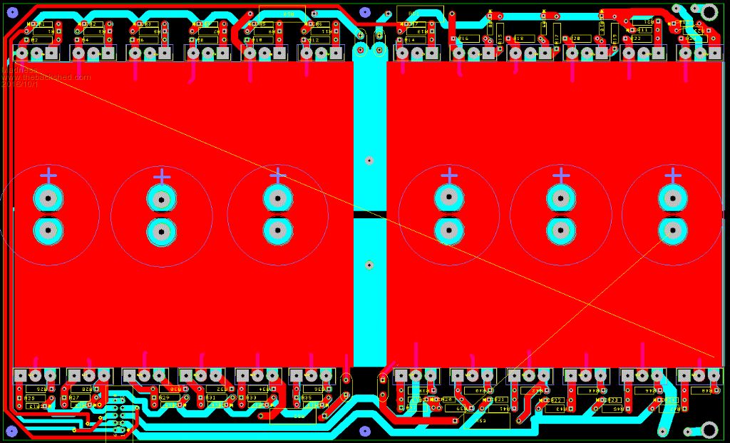 There are only 10 types of people in the world: those who understand binary, and those who don't. |
||||
Grogster Admin Group Joined: 31/12/2012 Location: New ZealandPosts: 9308 |
Thanks for posting your image - it is very useful for comparrision. My altered one: 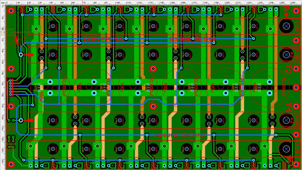 Back to two big ground-planes(one positive, one negative). This version only has 16 links to make with 3mm copper rod, instead of about 30 or so with the image on the previous page. I am seriously considering 2-ounce now, and perhaps another layout reshuffle.  What wattage are you using for the resistor in the snubbers? The 47R/1nF RC filters on the two toroid output lines..... Smoke makes things work. When the smoke gets out, it stops! |
||||
Madness Guru Joined: 08/10/2011 Location: AustraliaPosts: 2498 |
The Snubbers are 47R2W 103 3KV Keep in mind that the original design which mine above essentially is, uses the heat sinks as conductors for DC + in and on the bottom side of the image above the heat sink is split in 2 for the output to the Toroid. This reduces greatly how much current needs to flow through the PCB. There are only 10 types of people in the world: those who understand binary, and those who don't. |
||||
oztules Guru Joined: 26/07/2007 Location: AustraliaPosts: 1686 |
Grogster,.... you will build more than one... trust me it is a sickness. Once you see how they go in real life, you will just have to build a better one... and then a nicer one... and on it goes.... the mob I use allows 5 boards of larger size 2oz for a full size 15kw powerjack/clockman size... 300x200 $110usd gets it for 5, plus shipping. Note: Don't use DHL if in remote area, they add $30 extra.... use EMS... faster and same price more or less without the $30 excess... 5 boards this size and thickness are quite heavy. You will use probably 2-3 for you, and have a few spares. Or even cheaper, buy one from clockman.... they work just fine. This is from pcbway 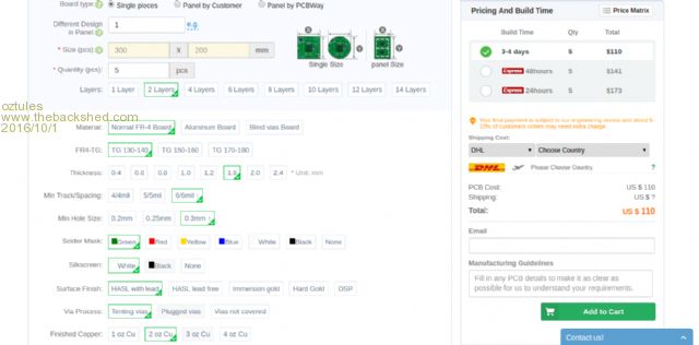 It is a sensible layout, and uses the heat sinks as power connection points for transformers and pos. However, yours looks very interesting... but gee I would struggle to get it nicely fabricated... I aint that good. .............oztules ps... considering the price of an inverter that could match these things, $500 per board would be still dirt cheap.... or clockman supplies all the boards ( fan, power and control) for a pittance anyway. No I am not a pimp for clockman, but it is the cheapest way to get it running for a single unit that will work without a problem, and very cheaply for a one off.. as you can see from the prices for boards of this thickness. Village idiot...or... just another hack out of his depth |
||||
Grogster Admin Group Joined: 31/12/2012 Location: New ZealandPosts: 9308 |
LMFAO!!!!    Oh dear..... You're probably right though.  Your other points are noted. Smoke makes things work. When the smoke gets out, it stops! |
||||
Grogster Admin Group Joined: 31/12/2012 Location: New ZealandPosts: 9308 |
Just a little update - I don't have much time to play with the inverter project at the moment - see "Lightning is fun...." thread. However, I was able to find about 30 seconds tonight to assemble the feedback board: 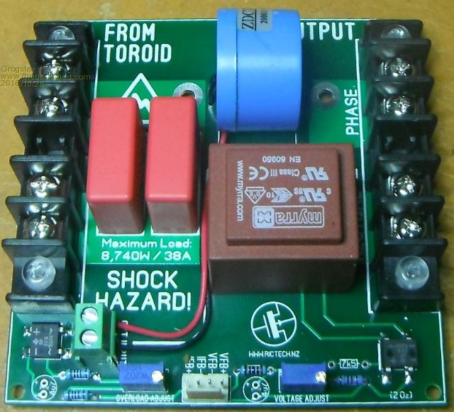 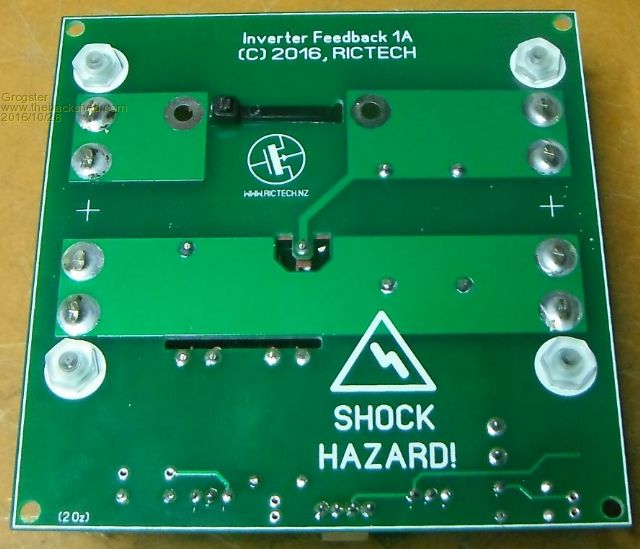 This board is designed to be capable of well over 8kW if ever needed. In my intended setup, this won't be required, but it allows me to upgrade later and keep the feedback board the same for pretty much any size inverter I ever plan to make. Note that in these photos, I have not fitted the 7k5 resistors for the voltage feeback as I don't have any of that particular value, and also the thick wire for the phase through the C/T is not installed - perhaps tomorrow. Smoke makes things work. When the smoke gets out, it stops! |
||||
oztules Guru Joined: 26/07/2007 Location: AustraliaPosts: 1686 |
The 7k5 is not terribly critical, and in fact is what I used as my excess/spare transformers were around the 14v mark... if yours are 12v, then the value may need to be changed to get the small AC range where you want it. With the components I used, the pot range was about 30vac for full 270 degrees... ie 220-250vac. ..........oztules Village idiot...or... just another hack out of his depth |
||||
Grogster Admin Group Joined: 31/12/2012 Location: New ZealandPosts: 9308 |
The transformer is 2x 12v windings, but only about 1.1VA(90mA), but I expect that to be fine, as we are only wanting a reference voltage and not really any current to speak of. I have left off the caps - did you or everyone else ever decide if those caps were to stay or go in the end? Smoke makes things work. When the smoke gets out, it stops! |
||||
oztules Guru Joined: 26/07/2007 Location: AustraliaPosts: 1686 |
Yes it uses virtually no current... it is the range that I was referring to... you may have to change the 7k5 anyway with 12v transformer. Caps are required to stop spurious operation. ........oztules Village idiot...or... just another hack out of his depth |
||||