| |
  Page 3 of 3 Page 3 of 3 |
| Author |
Message |
oztules

Guru

Joined: 26/07/2007
Location: AustraliaPosts: 1686 |
| Posted: 05:04pm 17 Sep 2016 |
 Copy link to clipboard Copy link to clipboard |
 Print this post |
|
Yep, thats it!
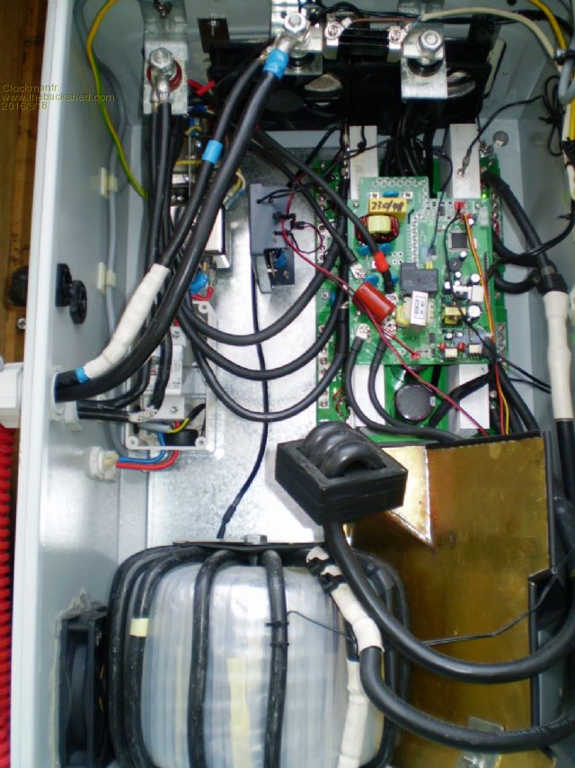
240v from the secondary goes to the two left terminals, and your output load goes to the right side of the capacitor.
It uses the 240v to get the voltage stable, and uses the current through that small current transformer for measuring the power output.
With out this, it will drive the scaling from zero to full, as it soft starts from zero to into the heavens at flat out(maybe up to 350vac).... probably saturating up there causing the current flush.
Fix that and your probably good to go.
There are three pins to the right of the cap, thats the outputs op/L and op/N... P7 is the earth point.
..... and yes, ALL the power goes through these pins, it is not just a voltage reference like the 8010 I did.... the secondary goes straight to the left two terminals.
Maintx-n is neutral from transformer, and Maintx-l is live from the transformer secondary.
It only matters for charger /ups transfer which 240v secondary wire is which.
For straight inverter operation, it makes no difference to the polarity. ( need to know primary and secondary orientation to match the wave form for ups / charger operation)
Your outputs are then the o/p N and o/p-L going to your output terminals.... P7 is earth point.
If you check the board, the maintx-L goes through the CT to op/L and out, and the maintx-N terminal goes directly to op/N... and thats it
You should be good to go from there.
..............oztulesEdited by oztules 2016-09-19
Village idiot...or... just another hack out of his depth |
| |
Clockmanfr

Guru

Joined: 23/10/2015
Location: FrancePosts: 429 |
| Posted: 08:42pm 17 Sep 2016 |
 Copy link to clipboard Copy link to clipboard |
 Print this post |
|
This is a 'OzInverter' with the Power Jack Cards/PCB's.
Yes the 230vac from the secondary, here I am using 10mm/2, on the torroid goes to the PJ control card, in this photo they are at the bottom of the PJ Control PCB.
Then the 2 output goes direct to EMC filters, those 4 silver metal cans, then a 40a RCD.
I never liked having the full AC from the torroid using the PJ Control card, so with the New 8010 'OzControl' board it just handles minimum AC. Therfore we can keep the board smallish, gentle, and lightweight.

Everything is possible, just give me time.
3 HughP's 3.7m Wind T's (14 years). 5kW PV on 3 Trackers, (10 yrs). 21kW PV AC coupled SH GTI's. OzInverter created Grid. 1300ah 48v. |
| |
gpalterpower

Senior Member

Joined: 19/07/2009
Location: AustraliaPosts: 175 |
| Posted: 09:30pm 17 Sep 2016 |
 Copy link to clipboard Copy link to clipboard |
 Print this post |
|
Thanks guys, so just to make this clear for myself, because I posted the photo up side down.  The secondary winding goes direct to the MAINTX L AND N (P5 AND P6) and the output come out of P3 and P4. P3 will be my active. P7 goes to earth/chassis. The secondary winding goes direct to the MAINTX L AND N (P5 AND P6) and the output come out of P3 and P4. P3 will be my active. P7 goes to earth/chassis.
I think I have a few filters lying around from the original inners of the inspire. Are they a necessary item to include in the box or will it run ok without them ?
Also the small single black lead from the control card with a 8mm terminal on the end. It goes to Batt -ve?
Thanks Marcus
if it aint broke dont fix it!! |
| |
gpalterpower

Senior Member

Joined: 19/07/2009
Location: AustraliaPosts: 175 |
| Posted: 10:44pm 17 Sep 2016 |
 Copy link to clipboard Copy link to clipboard |
 Print this post |
|
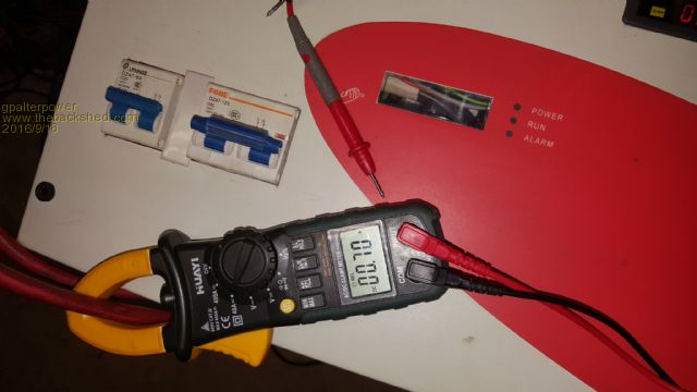
Ok. So I hooked all that up Annnnd....it works. Yay!   Soooooo happy. Thank you all for your help. A special thanks to you Oz for your input! Had to check out the idle draw. 0.7 A on 24v equals 17w. Soooooo happy. Thank you all for your help. A special thanks to you Oz for your input! Had to check out the idle draw. 0.7 A on 24v equals 17w.
..could that be right?? Seems to good to be true. Would one extra turn on the choke make that difference? Will do some more tests in the morning. Hooked up the fluro lamp. Nice. Just a light hum from the choke I suspect.. Beautiful.

if it aint broke dont fix it!! |
| |
oztules

Guru

Joined: 26/07/2007
Location: AustraliaPosts: 1686 |
| Posted: 10:48pm 17 Sep 2016 |
 Copy link to clipboard Copy link to clipboard |
 Print this post |
|
.....and sometimes it just works.... 
.........oztules
Village idiot...or... just another hack out of his depth |
| |
Madness

Guru

Joined: 08/10/2011
Location: AustraliaPosts: 2498 |
| Posted: 10:50pm 17 Sep 2016 |
 Copy link to clipboard Copy link to clipboard |
 Print this post |
|
One of those light bulb moments 
There are only 10 types of people in the world: those who understand binary, and those who don't. |
| |
gpalterpower

Senior Member

Joined: 19/07/2009
Location: AustraliaPosts: 175 |
| Posted: 02:17am 18 Sep 2016 |
 Copy link to clipboard Copy link to clipboard |
 Print this post |
|
Possibly a fluro lamp moment!
if it aint broke dont fix it!! |
| |
gpalterpower

Senior Member

Joined: 19/07/2009
Location: AustraliaPosts: 175 |
| Posted: 07:03pm 18 Sep 2016 |
 Copy link to clipboard Copy link to clipboard |
 Print this post |
|
A bit more testing this morning with some heavier loads. Heap more fluro lamps, a drill, grinder and a hair dryer. It seemed the more load the noisier it got. Off with the lid and was fairly easy to locate the culprit. It was the choke. With the aid of a lengthy fibre stick, I gently pushed and nudged the choke sideways and was amazed how quiet it became. The only fix was to completely varnish the winding and stop them from moving around. Something I should of done originally, knowing how much windings can move!
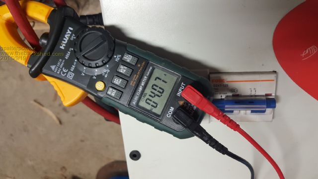
I wondered while I had the choke removed, how much more power would be consumed if it was bypassed. Some simple changes in the connections and turned it on. WOW! It had jumped to just over 4A. Amazing job that choke does!

Choke varnished and reassembled and it is as quiet as church mouse. Still drawing about 0.7A . 
Marcus
if it aint broke dont fix it!! |
| |
Madness

Guru

Joined: 08/10/2011
Location: AustraliaPosts: 2498 |
| Posted: 07:41pm 18 Sep 2016 |
 Copy link to clipboard Copy link to clipboard |
 Print this post |
|
When you consider how much AC current is flowing through it there is going to be quite a magnet field.
There are only 10 types of people in the world: those who understand binary, and those who don't. |
| |
Clockmanfr

Guru

Joined: 23/10/2015
Location: FrancePosts: 429 |
| Posted: 09:43pm 18 Sep 2016 |
 Copy link to clipboard Copy link to clipboard |
 Print this post |
|
Excellent, and well done Marcus. 
I will be soon testing the pin6 start/stop OzControl board. But I have a few questions for Oztules on that, espeacaially that 1k5 resistor acting on the 5v+ to negative on the Pin 6. I will post separately with my simple questions.
The start/stop using the temp sense on the OzControl board seems to be a rock solid action.
Everything is possible, just give me time.
3 HughP's 3.7m Wind T's (14 years). 5kW PV on 3 Trackers, (10 yrs). 21kW PV AC coupled SH GTI's. OzInverter created Grid. 1300ah 48v. |
| |
Madness

Guru

Joined: 08/10/2011
Location: AustraliaPosts: 2498 |
| Posted: 09:52pm 18 Sep 2016 |
 Copy link to clipboard Copy link to clipboard |
 Print this post |
|
1.5 K resistor is a pull down to ground so it turns off more reliably.
There are only 10 types of people in the world: those who understand binary, and those who don't. |
| |
oztules

Guru

Joined: 26/07/2007
Location: AustraliaPosts: 1686 |
| Posted: 10:14pm 18 Sep 2016 |
 Copy link to clipboard Copy link to clipboard |
 Print this post |
|
A spst switch that turns pin 6 on and off with ground OR 5v will work fine I suspect.
The resistor and the +5v and a spst switch does not work terribly well....
The resistor gives you pull down, but degrades the voltage slightly, and I think this is what makes it iffy with longer leads.... but with a stdp switch, should perform as expected. ( won't need resistor, as grounded by switch.
Have done some tests with the current shut off with the SCR. On a small unit works fine, BUT you will need more voltage than +5v to drive the SCR to turn the temp pin off.
The SCR will drop .7v or so across it's junctions when conducting which took my 5v down to 4.3v... which is not enough to trigger the temp pin... so used a 1k8 and 6v2 zener to provide the SCR voltage... then works very fast and perfectly so far.... shorted it out dozens of times... but this is only a bench test of a single fet board, and small ( 500w) EI transformer..... looking at the scope, there is no quibble, it is instant off... so should be ok ... probably not needing to use the driver pins.. will see later when some 10000uf caps turn up
..........oztules
Edit.... How did your power tests go with some real solid loads?Edited by oztules 2016-09-20
Village idiot...or... just another hack out of his depth |
| |
gpalterpower

Senior Member

Joined: 19/07/2009
Location: AustraliaPosts: 175 |
| Posted: 10:07pm 19 Sep 2016 |
 Copy link to clipboard Copy link to clipboard |
 Print this post |
|
I had the inverter running all day today. Started on light loads and increased to a grinder, pedestal drill and a small 1500w oven. Not all at the same time. Seems to work on these ok. Still running silently. I then tried to start a 2hp compressor. Hmmm. That was a no go! Just hummed so I turned it off. I'm going to borrow the CRO from work and see what sort of waveform I get with increased loads!
The pin 6 start/stop topic should be interesting reading when it comes along. Is this something that is relevant to the PJ board or only for the Oz board shut down .
Marcus
if it aint broke dont fix it!! |
| |
oztules

Guru

Joined: 26/07/2007
Location: AustraliaPosts: 1686 |
| Posted: 10:19pm 19 Sep 2016 |
 Copy link to clipboard Copy link to clipboard |
 Print this post |
|
... very strange, should have easily run all those things, AND started the compressor at the same time if it was an 8000w board pair....
Check your input and out put voltages under load.... wondering if you have run out of head room combined with battery fade.... very odd.
The pin 6 thing is for the 8010 boards.
........oztules
Village idiot...or... just another hack out of his depth |
| |
gpalterpower

Senior Member

Joined: 19/07/2009
Location: AustraliaPosts: 175 |
| Posted: 01:29am 20 Sep 2016 |
 Copy link to clipboard Copy link to clipboard |
 Print this post |
|
Thanks Oz,
Ill do some more testing tomoz. The battery feed is coming from some distance just for testing purposes, so there could be a substantial voltage drop. I'll relocate the inverter closers to the main battery bank and see if there is any difference. So far I'm just happy in the fact that it works and that the idle current is fairly low. Ironing the bugs out day by day 
Marcus
if it aint broke dont fix it!! |
| |
oztules

Guru

Joined: 26/07/2007
Location: AustraliaPosts: 1686 |
| Posted: 02:13am 20 Sep 2016 |
 Copy link to clipboard Copy link to clipboard |
 Print this post |
|
Yep, looks like long run @24v.. so your currents would be very very high. 2hp = 1.5kw and start up will be probably about 6 times that..so 360 amps required.... long batt leads..... 
It is useful to remember, that the caps have to try to carry the losses in the leads, and so are subject to very much more ripple than you would want to have them overcome... ie skinny leads or long runs will stress your caps markedly... in fact if you run that at say 2kw for 30 mins, you may find the caps too hot to touch.
This will lessen their life by a very large margin..... so ideally use 48v for power, and try to keep them cool ( <50C) for long life.... ripple kills filter caps!
...........oztules
Village idiot...or... just another hack out of his depth |
| |
gpalterpower

Senior Member

Joined: 19/07/2009
Location: AustraliaPosts: 175 |
| Posted: 02:48pm 13 Oct 2016 |
 Copy link to clipboard Copy link to clipboard |
 Print this post |
|
Hi all,
Well I hooked the inverter up to a better power source and have had it running for approx 2 weeks now. Its been on permanently day and night although at night is just sitting there just idling away. In the morning it switches back to the grid a runs beautifully. You were right OZ . It handles those loads with good battery supply. It was running the microwave and washing machine and then the compressor kicked in ...no worries!
Ill still borrow the CRO from work and just see what sort of wave form there is.
As far as hickups, only the one is where the PJ board reached the inbuilt pre shut down temp setting, before my fan cut in. A slight adjustment on the settings and now cuts in earlier. Think I will fit another fan hooked internally to the 3 pin outlet at a later date but for now is working fine.
In all I am pleased with the opperation of the inverter and had fulfilled all my expectations. 
Marcus
if it aint broke dont fix it!! |
| |
oztules

Guru

Joined: 26/07/2007
Location: AustraliaPosts: 1686 |
| Posted: 09:21pm 13 Oct 2016 |
 Copy link to clipboard Copy link to clipboard |
 Print this post |
|
.... nice when a plan comes together.....
........oztules
Village idiot...or... just another hack out of his depth |
| |
gpalterpower

Senior Member

Joined: 19/07/2009
Location: AustraliaPosts: 175 |
| Posted: 02:04pm 14 Oct 2016 |
 Copy link to clipboard Copy link to clipboard |
 Print this post |
|
Sure is Oz! And thanks again everyone for all for your help.
Next project coming up soon!
if it aint broke dont fix it!! |
| |
gpalterpower

Senior Member

Joined: 19/07/2009
Location: AustraliaPosts: 175 |
| Posted: 03:02pm 07 Dec 2016 |
 Copy link to clipboard Copy link to clipboard |
 Print this post |
|
Hi all,
just a bit of an update on the inverter. It has been running sweeet for over 2 months now except for a slight hickup the other day. I was checking it and noticed that the batt leads to the inverter were getting hot. The closer to the terminals the hotter they got and with more load they were even hotter. Actually the terminal itself sizzled when I placed my wet finger to it. Maybe 50w or more losses! Not good!!
Puzzled I was I noted that the neg terminal was substantially hotter that the pos. After pulling off the front cover I found the terminals inside were fine, due to the cooling effect from the fan. This made me think why the neg was hotter than the pos. I looked at the situation for a while and realised my mistake. When I assembled the inverter I thought I was doing the right thing by using stainless steel 8mm bolts as terminal. Big mistake! Depending on the grade of stainless, there is a portion of Nickel, and due to its properties has some internal resistance. I should of realised at the time. Duh!! The neg post was 40mm longer as it supported one end of the shunt so it acted as a somewhat large resistor. I could of and should of just used cad plated mild steel at the time.
I have now rectified the situation by replacing with 8mm copper terminals. No heating issues what so ever. Problem solved.
Marcus
if it aint broke dont fix it!! |
| |
| |
  Page 3 of 3 Page 3 of 3 |

