|

|
Forum Index : Electronics : Please settle this discussion
| Author | Message | ||||
| lew247 Guru Joined: 23/12/2015 Location: United KingdomPosts: 1702 |
I am using this circuit with a pic32 I've been told it wont work because there is no ground for the transistor I say it will work fine because the module itself is the ground, power goes in, and comes out and to ground I've been told the only real way is to use an opto isolator which would be good, but overkill I think |
||||
| lew247 Guru Joined: 23/12/2015 Location: United KingdomPosts: 1702 |
Or is this a better circuit? |
||||
| lew247 Guru Joined: 23/12/2015 Location: United KingdomPosts: 1702 |
or I'm trying to use the pic pin as a switch to switch power to the HC-12 (or any module) on and off |
||||
| Gizmo Admin Group Joined: 05/06/2004 Location: AustraliaPosts: 5078 |
The 2nd circuit is better. High side switching can be problematic, low side is easier. Remember the transistors Base lead will need to be at least 0.6 volts above the Emitter output. To turn the transistor on hard, it should be higher, above 6 or more volts. Its all about voltage drop across the junctions and gain. Glenn The best time to plant a tree was twenty years ago, the second best time is right now. JAQ |
||||
| powerednut Senior Member Joined: 09/12/2009 Location: AustraliaPosts: 221 |
or you could use a pnp instead of the npn for the first circuit. |
||||
Grogster Admin Group Joined: 31/12/2012 Location: New ZealandPosts: 9308 |
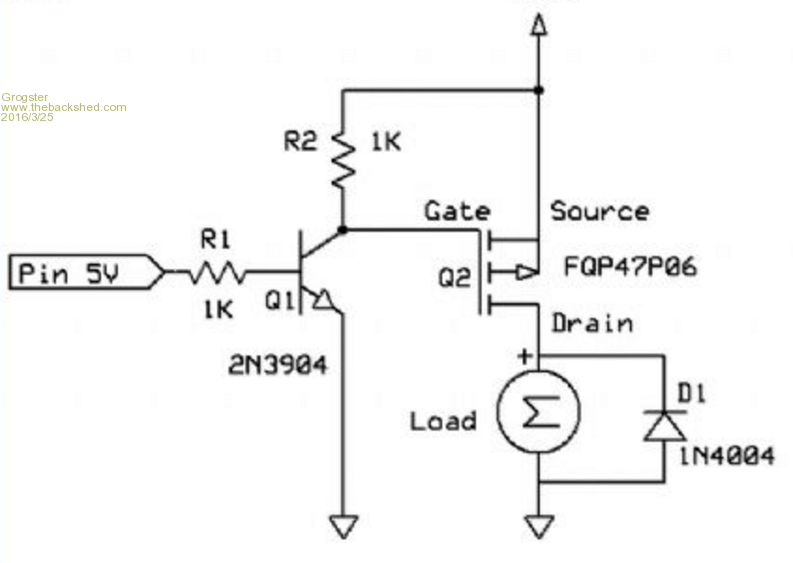
I agree with Gizmo. 2nd diagram with load in the collector circuit is the way to go. As you also mention, MOSFET is another option. I would be inclined to use the MOSFET idea. NPN/PNP are fine for switching LED's or other that don't really care much about losing some voltage(such as a bulb or relay). You will lose at least 0.6v across the transistor, if you use NPN or PNP, and when powering an HC12 - which I expect is the HC12 RF module - that 0.6v voltage loss could be an issue. It has been for me in the past. With RF modules, I tend to always go for a high-side switch, rather then a low-side switch, simply cos an RF module normally needs a good ground reference, and it is thus better to connect an RF module direct to circuit ground, rather then switching it's ground via a transistor to turn it on and off. A low-side switch on an RF module also means you have to isolate ALL the ground paths of the module to circuit ground - including the shield of the antenna or coax, any ground wires and also the case if it is metal or the aerial socket will act as a ground for the PSU. all of which is a pain in the posterior over just using a high-side switch. High-side MOSFET switch needs a 'Helper transistor' to pull the gate of the MOSFET low enough to turn it on: 
The advantage of this kind of arrangement is that it will work right down to only a couple of volts, and the ON resistance is tiny compared to a standard bi-polar transistor. This means that the switched device will see 99.9% of the full supply voltage - there is no 0.6v loss with the MOSFET method. Smoke makes things work. When the smoke gets out, it stops! |
||||
| Pete Locke Senior Member Joined: 26/06/2013 Location: New ZealandPosts: 181 |
....Or to keep it REALLY simple, use a 5v reed relay... Free from any old cordless phone  . . |
||||
| powerednut Senior Member Joined: 09/12/2009 Location: AustraliaPosts: 221 |
just in case you missed it, that is a p-channel mosfet in grogster's diagram. an n channel won't work there. If its an RF module, definately go with a high side switching arrangement. |
||||
| larny Guru Joined: 31/10/2011 Location: AustraliaPosts: 346 |
No you won't "loose 0.6 Volt across the transistor" if it is saturated. Vce is about 0.1 Volt if saturated. To saturate the transistor, you need the base current to be about 10 times the collector current. |
||||
| larny Guru Joined: 31/10/2011 Location: AustraliaPosts: 346 |
No, you won't loose 0.6 Volt across the transistor if it is saturated. So the NPN circuit in post 2 is quite adequate. When a transistor is saturated, the Vce will be about 0.1 Volt. In order to ensure that it is saturated, you need the base current to be at least one tenth of the collector current. For example, if Ic is 10 mA, then Ib needs to be at least 1 mA. In the circuit of post 2, R4 = 4.7k. The PIC will output about 3.3 Volt, so the base current will be about (3.3 - 0.6)/4.7 = 0.55 ma. Thus it will be saturated if the collector current is 5.5 mA or less. |
||||
sparksandsmoke Newbie Joined: 14/05/2015 Location: IrelandPosts: 12 |
I agree. Powerednut offered an appropriate solution earlier - a "high side" PNP BJT. |
||||
| larny Guru Joined: 31/10/2011 Location: AustraliaPosts: 346 |
Please note. My first post above was posted accidentally due to a web site anomaly. It is incomplete & has a typing error. Please ignore it and only read my second post. |
||||