
|

|
Forum Index : Electronics : inverter experiment pure sine EGS002
| Author | Message | ||||
Madness Guru Joined: 08/10/2011 Location: AustraliaPosts: 2498 |
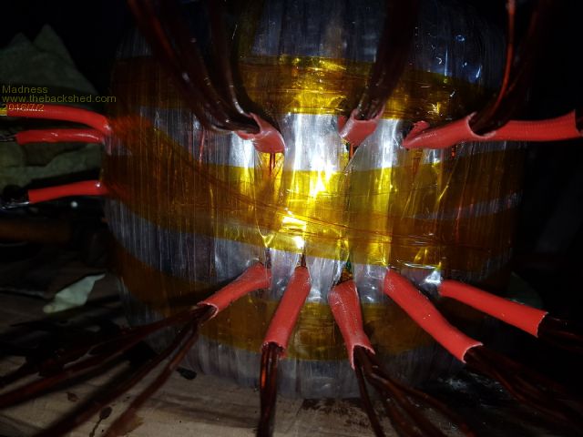
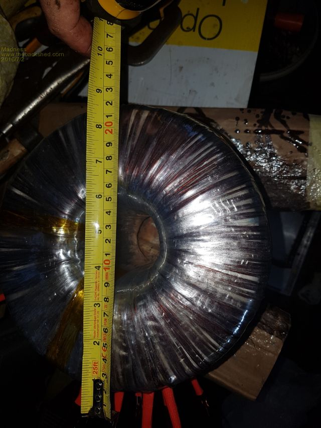
No Octopuses where harmed in the making of this Torroid. Finally finished sticking stuff through that hole, not that much more would get in there any way. 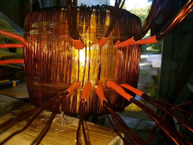
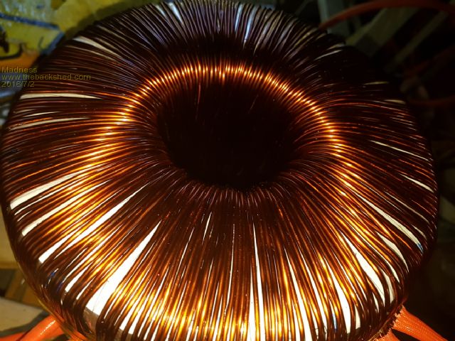
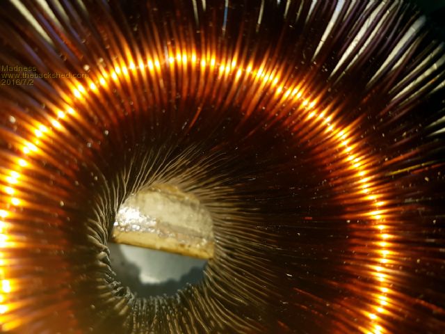
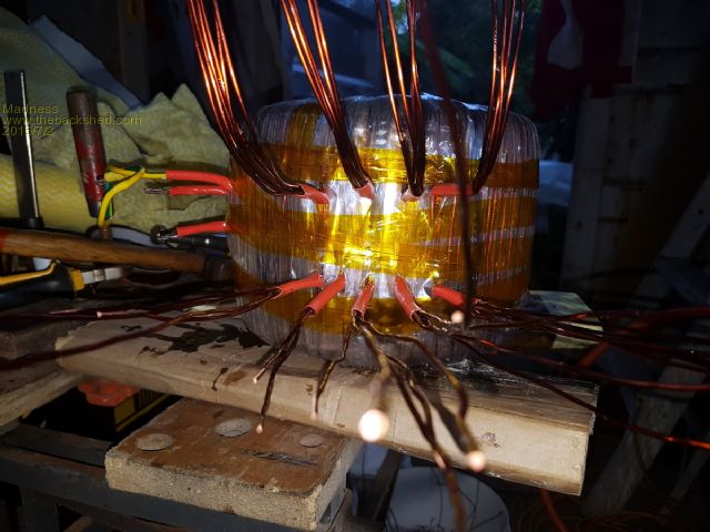
There are only 10 types of people in the world: those who understand binary, and those who don't. |
||||
oztules Guru Joined: 26/07/2007 Location: AustraliaPosts: 1686 |
What an effort..... tired just looking at it. Did you get the 60mmsq? I'm very impressed, and wonderinghow your fingers are doing after that effort. .........oztules Village idiot...or... just another hack out of his depth |
||||
| yahoo2 Guru Joined: 05/04/2011 Location: AustraliaPosts: 1166 |
I rate your new cephlapod class toroid.... 10 tentacles! I'm confused, no wait... maybe I'm not... |
||||
Madness Guru Joined: 08/10/2011 Location: AustraliaPosts: 2498 |
I got 21 x 2 mm wire so total of 66 mm square on the primary. Ended up with 2 and a bit layers of wire on the inside and 1 layer on outside. If anyone plans to copy what I have done, pay a lot of attention to getting the wires spaced out very evenly. They are not so easy to move around when you have 8 or 9 wires on there and the spacing is out. The paper guide I made on CAD software and put under the Mylar is a big help here. Secondary is 4 X 1.6 mm so total of 8 mm square. I think it would be possible to add 1 or 2 more on the secondary and still maintain the same ratio for the primary. But as you mentioned Oz, fingers are still and sore, my crook shoulder is aching and my back is stiff.  (Wife thinks I have lost the plot also) (Wife thinks I have lost the plot also)
Next is to connect all the primaries together, my plan is to bend the bottom one to the left and top to the right with about a 10 mm gap from the outside of the tranny and insulate them. So will end up looking like an old style exhaust manifold if that make sense. Then work on the box and the circuit boards. I am going to cut a hole under the transformer for a fan. On the top of the Aero sharp box I will put 10 mm spacers on each screw under the heat sink. this will leave a 10 mm gap so air can convect up out under the edge of the heat sink. This will also allow more clearance between the board and caps and the torroid. Very confident it will fit back in one box. The little ferrites arrived to go on the mosfet's, I will need to put a 3-4 mm spacer strip and insulation between the board and the mosfet's to allow room. Also will need insulation to stop them contacting the heat sink. There are only 10 types of people in the world: those who understand binary, and those who don't. |
||||
| yahoo2 Guru Joined: 05/04/2011 Location: AustraliaPosts: 1166 |
I would love a photo posted when you get to that bit Gary. I'm confused, no wait... maybe I'm not... |
||||
Madness Guru Joined: 08/10/2011 Location: AustraliaPosts: 2498 |
Will do, thinking about starting new topic for this build, might do that tonight. Nearly ready to etch PCB's too, has anyone tried the cold alcohol and acetone method to transfer toner on to a PCB? As shown here https://www.youtube.com/watch?v=HBIxvwZ_0og There are only 10 types of people in the world: those who understand binary, and those who don't. |
||||
oztules Guru Joined: 26/07/2007 Location: AustraliaPosts: 1686 |
If you want use the big heat sinks from the aerosharp, I did it here in the traditional mock up. here .........oztules Village idiot...or... just another hack out of his depth |
||||
Madness Guru Joined: 08/10/2011 Location: AustraliaPosts: 2498 |
Looks like you bought it, good job. There are only 10 types of people in the world: those who understand binary, and those who don't. |
||||
oztules Guru Joined: 26/07/2007 Location: AustraliaPosts: 1686 |
Village idiot...or... just another hack out of his depth |
||||
Madness Guru Joined: 08/10/2011 Location: AustraliaPosts: 2498 |
Hi Oz, have you compared that heat sink to the vertical external version you did? There are only 10 types of people in the world: those who understand binary, and those who don't. |
||||
oztules Guru Joined: 26/07/2007 Location: AustraliaPosts: 1686 |
Yes. It is about 3/4 or more the size of the original heat sink.... but due to it's configuration is very much easier to deal with effectively with cooling if extended high power is required. History shows the smaller PJ heat sinks with a fan will keep 6kw easily under control, these are twice as heavy, so will certainly do every bit as well. Tests have not shown the need for fans at this time, as extended runs of greater than 3kw have not been undertaken, due to weather. Daily 3kw for 2-3 hrs are no problem, but it is cooler here than up there. In your case also this would be the easiest to use and control at high power. If the natural cooling did not work for the unit you are doing, then cooling fans will be problematic for a nice looking unit... will look odd I expect. Final information is that a clockman/pj style board is still probably the easiest to fabricate, and control... I'm going way again. ..........oztules Village idiot...or... just another hack out of his depth |
||||
| jdevine82 Newbie Joined: 01/09/2016 Location: AustraliaPosts: 13 |
Hi all I have been scouring the different forums to try and get an actual schematic for the main board. I didn't succeed and I think Oztules has said he just draws the circuit without one. I have reversed engineered the circuit(I think!) and put the complete project into kicad. I have drawn the version that oztules has with linear regulators but am going to do one with switchmode modules from ebay that are way more effecient. Here is a link git repo for ozinverter in kicad Public domain of course 
This is untested at this point but I will be getting some boards made shortly for myself. I like the silkscreen etc of a pcbhouse. This initial version is not pretty and the schematic is rough as it is a bit odd reverse engineering a circuit like this for me. Jason |
||||
| jdevine82 Newbie Joined: 01/09/2016 Location: AustraliaPosts: 13 |
Hi all just added a new repository of the same project with a modifed controlboard with a switchmode power supply. I also changed the pcb size to 10x10 as it is cheap with the pcbfab houses. This version will not sit on original powerstar/powerjack output mounting board but will plug into it. git repo oztulesmoded Jason. |
||||