| Author |
Message |
brucedownunder2
Guru

Joined: 14/09/2005
Location: AustraliaPosts: 1548 |
| Posted: 02:37am 25 Nov 2007 |
 Copy link to clipboard Copy link to clipboard |
 Print this post |
|
Hello Crew,, Domwild gave me this reg a few years back --Thanks Dom.
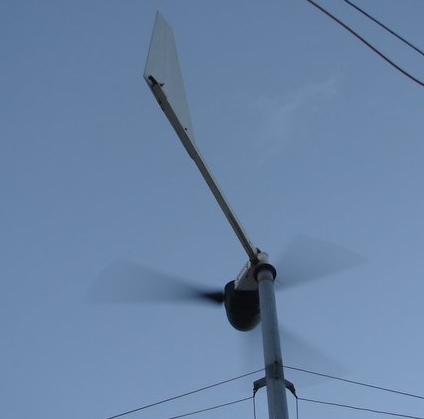
Anyhow ,,I'd like to control my new 48V dual F&P flying machine,,,so can someone out there post some recommendations concering the values of components to be changed regarding the "onboard components"..
Also,, I'm hoping for around 800 watts or more when I finish my second Neo Rotor,,, could some of u think about recommendations concerning power on the critical parts of the board and maybe removing the Mosfets to a heatsinked part away from the board..
Thank You ,
Bruce
Bushboy |
| |
GWatPE

Senior Member

Joined: 01/09/2006
Location: AustraliaPosts: 2127 |
| Posted: 01:52pm 25 Nov 2007 |
 Copy link to clipboard Copy link to clipboard |
 Print this post |
|
Hi Bruce,
My picaxe dump load controller will probably be available on commission order, once I get to have a pro board made. double sided, and silk screened etc.
The cost of modifying the oatley could exceed its value.
I am currently looking at a 50V controller for a windmill in another application.
cheers, Gordon.
become more energy aware |
| |
Highlander

Senior Member

Joined: 03/10/2006
Location: AustraliaPosts: 266 |
| Posted: 08:01pm 25 Nov 2007 |
 Copy link to clipboard Copy link to clipboard |
 Print this post |
|

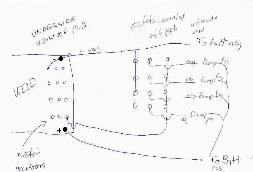
Hey Bruce this is how I did mine, use heavy wire though.
Don't know how to change to 48v
Central Victorian highlands |
| |
brucedownunder2
Guru

Joined: 14/09/2005
Location: AustraliaPosts: 1548 |
| Posted: 08:29pm 25 Nov 2007 |
 Copy link to clipboard Copy link to clipboard |
 Print this post |
|
Thanks Gordon and Highlander--- yes,I'd certainly re-locate the mosfets to a heatsink off the board and use a larger size conductors.
The 48v must be doable but as Gordon said ,,the removal of so many components and replacement could run into more than it's worth..
Will speak to ross on the irc in a few minutes about his.( you guys are welcome on the irc chat channel ,if you have the time).
Thanks for the feedback
Bruce
Bushboy |
| |
GWatPE

Senior Member

Joined: 01/09/2006
Location: AustraliaPosts: 2127 |
| Posted: 01:56am 26 Nov 2007 |
 Copy link to clipboard Copy link to clipboard |
 Print this post |
|
Hi Bruce,
The values for mods 48V oatley.
R9 47k maybe 0.5W
the power rating of Q1 may be exceeded
R1 330k probably 0.25W still
have to check voltage rating on Q1-4
Mosfets need to be 100V with similar current rating.
These values are approximate as I don't have an oatley to test with. Don't forget to add some positive feedback between pin 3 or 4 of IC2 and pin 2 of IC1. try 220k and test the hysterysis. increase value to decrease hysterysis and vice-versa.
I hope this helps.
You can always ring me to clarify.
cheers, Gordon.
become more energy aware |
| |
martinjsto

Senior Member

Joined: 09/10/2007
Location: AustraliaPosts: 149 |
| Posted: 05:59am 30 Dec 2007 |
 Copy link to clipboard Copy link to clipboard |
 Print this post |
|
hi bruce, just noted your post, i found that you can use the regulator circuits found on this site under the other "trouble with oatley regulator" post for most current draws.
i dont use the circuit to switch the load as this limits the current u can use, unless you modify as sugested above, even then i have found the mosfets seem to have trouble swithching or you need cooling fans and large heasinks,
i found it better to use the circuit to operate only a relay, you can use large relays to swithc on or off larger currents the relay does all the hard work saving the circuit. what do others think of this, i have found it very successfull and have never had a burnout.
martin
free power for all
McAlinden WA |
| |

