|

|
Forum Index : Electronics : help with circuit
| Author | Message | ||||
| BobD Guru Joined: 07/12/2011 Location: AustraliaPosts: 935 |
Ron for the moment please ignore the voltmeter at P3. Your circuit as it is now is working correctly. Now is time to start adding back the big transistors. Put them back one at a time. Make only small changes and test after each change. If you get a problem then you know where to look. Document each step as you do it if there is any doubt about your memory. Bob It is now 12:36am in Australia so I'm going to bed. |
||||
Downwind Guru Joined: 09/09/2009 Location: AustraliaPosts: 2333 |
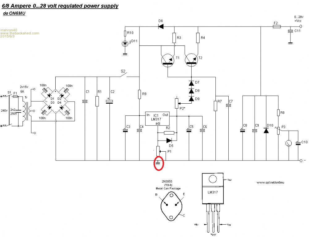
I do really question how good the circuit design is to start with. It appears to me at a quick glance to be not that well designed or should i say over designed for its use. For example why have D7, D8, D9 and P2? Really its a simple power supply that is over complicated in my view.(then there is other areas of design i also question) You do realise that you need at least 2 volts higher on the input voltage to what you can expect on output voltage. There is no value given for C2 and i well expect it to be way too low for the circuit, and should be around 3000 - 5000uF, some may disagree, but for a general purpose power supply it needs to be that high. I would suggest scrapping the design and building a better power supply like this one. http://www.thebackshed.com/windmill/articles/VariablePowerSupply/TheBackShed723Reg.gif There should be a full write up on it on the front page of the forum, as i designed it and posted it, and Glenn added it to the front page projects, albeit some of the links appeared broken when i looked. Pete. Sometimes it just works |
||||
| irishron40 Senior Member Joined: 22/09/2014 Location: IrelandPosts: 251 |
this is done to be able to get a reading as low as 0 volt on the meter which will also take that away from the max volt output reading C2 is two capacitors off 4700uF/50v each bob , you said to ignore the voltmeter at p3. but this is confusing me even more. lol I thought that is where you were suppose to connect the volt meter so you could trim it with the p3 to callibrate it |
||||
| irishron40 Senior Member Joined: 22/09/2014 Location: IrelandPosts: 251 |

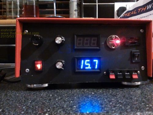
here is my second project nearly finished. i did remove the 3 diodes so my voltage went up to 15.7. just have to connect amp meter and shunt. I only have the one tip3055 connected as I need to get bolts and nuts for second tip3055 I had 2 volt drop when i connected a motor drawing 2 amp would the voltage drop me less when I have second tip3055 wired up? thanks ron |
||||
| rustyrod Senior Member Joined: 08/11/2014 Location: AustraliaPosts: 121 |
Gents, QUOTE Calibration: - Get your hands on a calibrated digital meter or a good analog meter and measure the voltage at the output of the power supply. - Turn P1 to maximum (maximum voltage of our power supply). - Adjust P3 till the meter needle shows maximum result (end scale) - If you want to calibrate the scale, turn P1 to several voltages (like every volt) and confirm each time with your calibrated voltage meter. Make a mark on your power supply meter-scale to calibrate the meter. - You should see equal spaced voltage marks on your home-made scale if your meter is a linear type. The parts required do not explain the meter. It is drawn analogue. ?Analogue meter ? 50ua? 0 to 20 volt? Irishron has a digital??? R8 p3 c10 not needed??? maybe??? To Irishron, Copied from site. (? is this is written in chinkenese) "Note: The collectors of the finals needs to be soldered with a wire all together if the transistors even if they are isolated from the heatsink or not. If you do not isolated the finals from the heatsink, then please make sure the heatsink does not make contact with the chassis (metal casing where you plan to build the PS into)" So INSULATE THE TRANSISTORS CAREFULLY To test transistors - connect a 5 or 6 watt 24 volt bulb between junction of switch/R9/R10/D6 and the Collectors (the case)of your transistors. If this bulb lights up you have a problem. Disconnect R3 and R4 - light should be out. If "on" you have a problem with transistors. If the light is "out" you should be able to vary the voltage on the emitters. To test for shorts/overload connect some 5 or 6 watt 24 volt bulbs between E and R3 and E and R 4. If bulbs light up you got a problem with some thing after the transistors. Then as Gizmo said "Sounds like a short on the output somewhere. Check D10 is facing the correct way. Start removing parts of the circuit until it works, suspect anything after the transistors, look for shorted PCB tracks. AND if D6 is wrong way around the output will not be able to be varied. Always Thinking |
||||
| irishron40 Senior Member Joined: 22/09/2014 Location: IrelandPosts: 251 |
I am just a total beginner who has a passion for electronics, but still has it all to learn. I am always polite , and am grateful for all explanations. I dont think there would be any need for sarcasm. ron |
||||
| Gizmo Admin Group Joined: 05/06/2004 Location: AustraliaPosts: 5078 |
I dont think Rod meant to be sarcastic. "chinkenese" if I'm not wrong is slang for a poor english translation of chinese, something we see pretty often on cheap products from China. Glenn The best time to plant a tree was twenty years ago, the second best time is right now. JAQ |
||||
| irishron40 Senior Member Joined: 22/09/2014 Location: IrelandPosts: 251 |
in that case I appologise for my misunderstanding/ ron |
||||
| rustyrod Senior Member Joined: 08/11/2014 Location: AustraliaPosts: 121 |
I got the sentence from this site The collectors of the finals needs to be soldered with a wire all together if the transistors even if they are isolated from the heatsink or not. Too many "if" So Cut "if the transistors" The collectors of the finals needs to be soldered with a wire all together even if they are isolated from the heatsink or not. Now it makes sence. The way the sentance was written, it was confusing to me. 
I was trying to find a source for the "buzzing" When you get the bolts, Are you going to insulate the transistors or insulate the heatsink? A suggestion for increased safety and a visible warning of overload or short in whatever you connect to the power supply. Add a headlight bulb with the two filaments wired in parallel between the below junctions. Around 100 watts is equal to approximately 8 amps.Then if there is a short, like when the leads dangle over the side of the bench and touch together, the bulb will light and save the fuse. When you wire in your amp meter, Will you connect it between the junction of R3 R4 D6 and junction of F2 C8 C9 D10 R8? Is it an analogue meter or digital? By the way, I have some combined digital volt/amp units and the amp shunt is in the NEGATIVE side. This makes them hard to wire up from multiple inputs to a single output. eg multiple solar panels. Each unit has to have it's own power source, with no common connections except the outputs. Even the solar regulators I have regulate the negative side. Confusing? So with these units I have would have to have the Amp shunt wired between C7 and C8 in the negative line with the red wire to the junction of F2 C8 C9 D10 R8 positive power. THEN powered by a 9 volt battery. Mine I do not think would work from the extra 12 volt regulator you have suggested. This still leaves the question, If Ron is using digital displays, Is the calibrating R8 P3 still required? My digital volt display units are accurate to within .01 of a volt. The bulb tests are still relevant when finding faults. How do you test/fix an electric fence in the rain? 
Disconnect the energizer. Get a battery charger and a headlight and a set of binoculars. Set headlight up a pole outside. Get mud boots and slosh in the mud. Work on fence, Check light with binoculars. When the light goes out you have fixed the fence. Go home and reconnect the energizer. Have something warming to drink.  Always Thinking |
||||
| irishron40 Senior Member Joined: 22/09/2014 Location: IrelandPosts: 251 |
this is getting far to complicated for me. lol I dont have buzzing with this transformer i am using now. 12volt regulator is only there to power my fan , and my usb phone charger port . and I did insulate the transistor from heatsink. I didnt bother with the current limiter. just wanna wire ampmeter to be able to see what a specific load is drawing just discovered that the shunt I have is a 100A one. and my meter is 0-50A Things never work out first time round lol thanks. ron |
||||
| irishron40 Senior Member Joined: 22/09/2014 Location: IrelandPosts: 251 |
Is this where meter and shunt should be connected rustyrod? on shunt it said to use the negative line thx ron |
||||
| rustyrod Senior Member Joined: 08/11/2014 Location: AustraliaPosts: 121 |
Hi Ron, In short "I haven't much experience with digital meters" My combi digitals do have the shunt in the negative. I have looked at a lot of eBay digital meters and YES, they all seem to have the shunt in the negative. So now you and I both need advice as the where is best to connect it in the negative line. Would the circuit be best to have the Amp shunt wired in between C7 and C8 in the negative line? Reason for this placement - The volt meter would be after the shunt and would reflect a truer indication of the output voltage. If the shunt was placed between the circuit and the output terminal THEN the voltage shown on the meter display would be the voltage before the shunt and therefore slightly MORE than the real output voltage. This difference will increase as the load increases due to the resistance in the shunt increasing with the load. Back to the question Gents, Where is the best place for Ron to put the shunt? Ron, Has your meter got instructions, information on which way to connect the heavy wires to the shunt? Has your display got 4 wires? Trust your instructions. How do I explain what is in my head? here goes, Say the shunt is cut into the negative line between C7 and C8 for example, the end connected to C7 will be negative and the end to C8 will be less negative, So connect the black wire to this C7/negative end and the other wire to the other end. Always Thinking |
||||
| irishron40 Senior Member Joined: 22/09/2014 Location: IrelandPosts: 251 |
Now Ive gotta try to get it into my head lolol I would love my ampmeter to read what amp I will allow ( limited) and also when no resistance on potentiometer that i can read what my load is drawing. |
||||
| rustyrod Senior Member Joined: 08/11/2014 Location: AustraliaPosts: 121 |
Ahh, this is what you mean "P2 will allow you to set the limit of the maximum available amps at the output +Vcc. When using a 100 Ohm/1watt varistat the current is limited to approx. 3 Amps @ 47 Ohm and +- 1 Amp @ 100 Ohms" Well this current in this part of the circuit between the wiper of P2 and the diodes will be quite small (Low) How would I set this up? mmm thinking.... Try this, disconnect the P2 wiper from the diodes connect your multi-meter set to 250ma in here. Red probe to P2 wiper. With no load on the power-supply output measure the current Connect a load eg car headlight. 60 watt. from formula 60 watts divided by 12 volts equals 5 amps. adjust power supply to 12 volts. read current at multi-meter. you may have to switch to the 10 amp selection It will not be more than 1 amp anyway. From this measurement you can calculate the "limit amps" I doub't you will need a 50 amp shunt here. The LM317 only good for 1 amp. "I Think" The gents with the knowledge to calculate the aspect ratio and the angles divided by something will soon correct me with the correct current draw. This will be good! The P2 with a pointer knob and piece of paper glued on the face of your cabinet could be marked to represent the approximate output limit. Still thinking, m m m something not quite adding up here. The current here will be low or nothing then only start to show as the output of the power supply is loaded. In the article it mentions measuring the resistance to set the output current. Next, I'm out. I'm confused. I would have to get my hands on it and do some tests. Due to your interest in this project I have started to gather components to make one too. Always Thinking |
||||
| geraldfryjr Regular Member Joined: 02/03/2014 Location: United StatesPosts: 61 |
Hi There!! I just found this thread and started following your project, I had wished I had found it earlier. I had done a study on this type configuration of a current boosted LM317 and you my find that it doesn't have very good regulation factor as you start to draw heavy loads from it. Here are a couple of threads that I was involved in and also a circuit that I designed along they way to help out a fellow DIYer. http://www.diyaudio.com/forums/power-supplies/264790-12-volt-30-amp-power-supply.html#post4123549 The circuit that I built is rock solid and very very low noise at approximately 50-100uv rms. Rather than me re-typing everything again check out this thread as I try to explain exactly what is going on and solved the issue along the way by just simply adding an opamp. http://www.diyaudio.com/forums/chip-amps/261125-lm3886-problem.html#post4053260 The circuit that I built doesn't go all of the way down to 0v since that would require a V- and my 18v transformer is not center tapped. I have also shown some methods later in the threads to get very high current regulation as well but I have not built the prototype of those yet. I had mention that I did make a regulator that worked up to 30-50 amps it used 4x2N3055's and an IRF511 to drive them. I don't have the schematic for it any more but the methods I have shown are basically the same and they can be found here, http://www.diyaudio.com/forums/chip-amps/261125-lm3886-problem-2.html#post4073963 I had started working on a very high current version and is why there are three examples but I haven't finished that phase of the design yet as I am not in need of such larger regulator at this time. But I will be some time soon!! ;) In the above post I had provided the ASC files for LTSpice as well should you want to check out the simulations. I would be happy to answer any questions that you may have at anytime. This is the schematic of the final design that I am using at this time and I can get about 3.5-4 amps out of it at 12v-14v or so due to the small 18v 2amp transformer that I have. But, I feel that it should work fine up to double that current the way it is if I used a transformer with a larger VA rating. You must use a heatsink on the transistor and the bigger the better. http://www.diyaudio.com/forums/chip-amps/261125-lm3886-problem.html#post4064510 I get absolutely no voltage variation when I repeatedly connect and dis-connect a low resistance load (1-4 ohm) to the supply except for a quick transition pulse that is common under such conditions but no variations or instability as confirmed by my scope. Since the supply is controlled by a voltage into a high impedance input, I am planing to use a PIC controller to add some memory features for voltage settings. Else the voltage is simply set by an external voltage or by a pot that is connected to a voltage reference chip. Cheers !!! :D jer :) Keep on DIYin' !!!  |
||||
| irishron40 Senior Member Joined: 22/09/2014 Location: IrelandPosts: 251 |
Grrrr just blown the 10Amp fuse as by accident I shortend the positive and negative. after i replaced the fuse I have output . but cant adjust it. Changed the lm317. ( no change) Changed the zener d5 ( no change ) changed R2 resistor (no change) before I start changing more do you have any thought on this please? 
thx ron |
||||
| irishron40 Senior Member Joined: 22/09/2014 Location: IrelandPosts: 251 |
problem sorted. it was the tip3055 just wonder would a 10 amp fuse be to big , as the tip 3055 also blew? maybe a 7.5 amp? thx |
||||
| geraldfryjr Regular Member Joined: 02/03/2014 Location: United StatesPosts: 61 |
You would better off using the TO-3 version of that transistor. I have blown many of them in one of my amplifiers were I had used them in a pinch. Not often have I blown the heavier package type but it does happen occasionally. jer :) Keep on DIYin' !!!  |
||||
| irishron40 Senior Member Joined: 22/09/2014 Location: IrelandPosts: 251 |
I would have thought a fuse should had protected that fromhappening. thx ron |
||||
| geraldfryjr Regular Member Joined: 02/03/2014 Location: United StatesPosts: 61 |


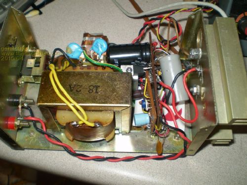
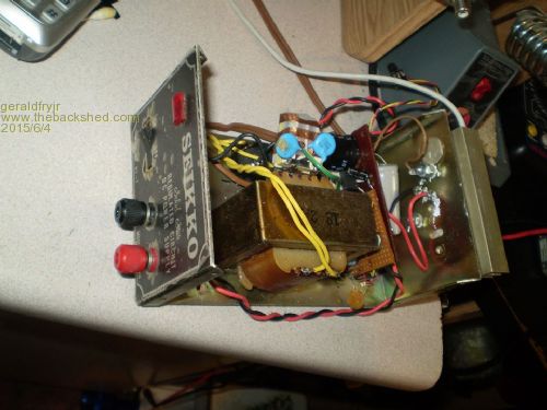
If you read through the threads I had posted the OP was having the same issues as well. Some of it turned to be DIYer error and other times it was not. It was the time it was not got me really interested in the project. I had suggested a few possibilities as to why this was happening, although we never really nailed down the exact reason why, and,I don't have enough parts laying around to risk finding out right now. But the circuit I made I have only blown one transistor due to an unexpected short when I wasn't looking and that device was the original TO-66 version NPN that was intermittent to begin with. When I switched to the TO-3 NPN's I had almost burned one up before I had it on some sort of heatsink but it did miraculously survive. The ones I have don't have any numbers on them anymore but the they are just remarked 2N3055's from DEC or maybe even their heavier duty counterpart. The heatsink that I am using is not very big but it survives a short with 3.5 amps of current for quite some time and yes it does get very hot. As it is now it can still get pretty hot if i leave the supply shorted for too long I am planning on mounting a small 2" fan on it as soon as I run across the one that I have in my pile of parts. My big supply was very well heatsinked and I could pull 50amp at 9v or 30amps at 15v all day long. I made it from a 450 watt UPS transformer that I had, it never got hot enough to need a fan although I had some on it just in case. I used it to make electromagnets out of some of the spools of wire and telephone cable I had laying around!! He,he,he,he The circuit you are using doesn't provide for any type of current limiting on the output device, there is no feedback from the output to control the LM317. At some point when you draw enough current from it (in my theory is) that the Base voltage of the transistor could be exceeding its maximum rating of 7v. This because as you start drawing more current the emitter is much closer to a ground potential, and the LM317 is still trying to feed the base at 12v (or something over 7volts) and then POOF!! jer :) Your supply looks Great just for the record here are two shots of mine the day I was ready to put the cap back on it. :) Keep on DIYin' !!!  |
||||