
|

|
Forum Index : Electronics : ATX PSU to Power Supply - Shunt Size?
| Author | Message | ||||
wallablack Senior Member Joined: 10/08/2011 Location: AustraliaPosts: 164 |
Hi All, I am in the process of converting an old 300W ATX PSU from an old computer into a bench top power supply which will be more than handy. Plan is is to have a stable 12V and 5V power supply. Both the 5V and 12V will run into a voltage converter (boost buck I think they call them)so I can have a bit of regulated power. 
The ATX conversion was pretty easy thanks to Dr. Google. My issue is is that I have noooo idea what size shunt to use for the amp meter below. WHAT SIZE SHUNT DO I USE? Ill have three of these... One measuring 5V One measuring 12V, and One measuring "Boost Buck" OUTPUT. 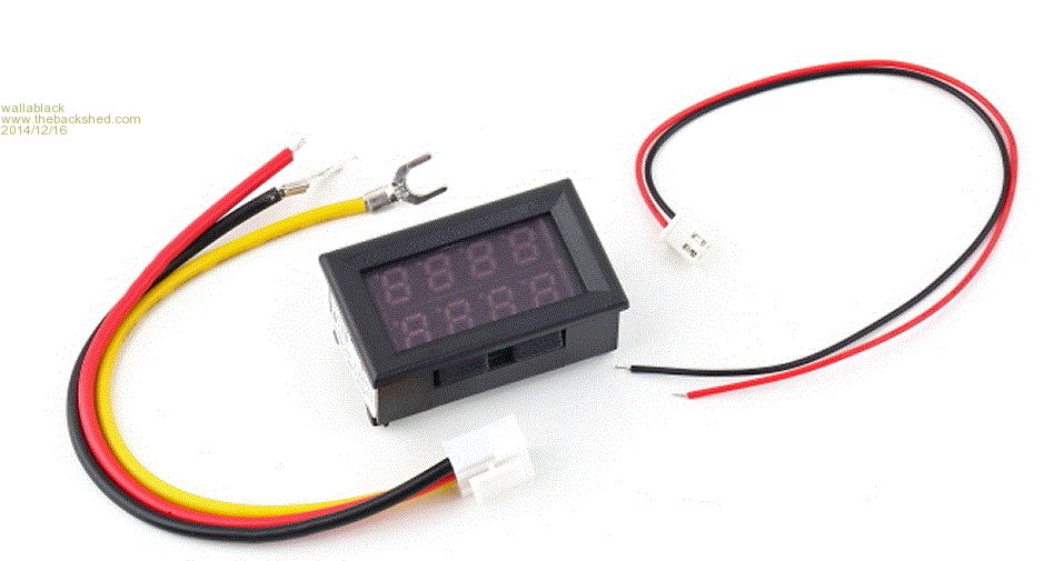
Specs are: Operating voltage:DC 4.5 ~ 30V Measure voltage: DC 0 ~ 100V Minimum resolution(V): 0.1V Measure current :DC 50A (require external shunt) Minimum resolution(A): 0.1A Operating Current: <20mA Display: three 0.28\" LED digital tube Display color: Red (dual display) Dimensions: 48 x 29 x 21mm Mounting cutout: 45.5 x 26.5mm Refresh rate: about 500mS / times Measure accuracy: 1% (± 1 digit) Operating temperature: -10 to 65° c Operating Humidity: 10 to 80% (non-condensing) Working pressure: 80 to 106 kPa The wiring is as follows...Not much to do with the shunt size but I thought I'd throw it in for kicks. Black line (thin): vacant or buck circuit (module) negative Red line (thin): power supply+ Black line (thick): COM, common measuring Red line (thick): PW+, measuring terminal voltage input positive Yellow line (thick): IN+, current input+ (Please refer to the wiring diagrams for more details) Thanks in advanced.... Progress on the power supply. 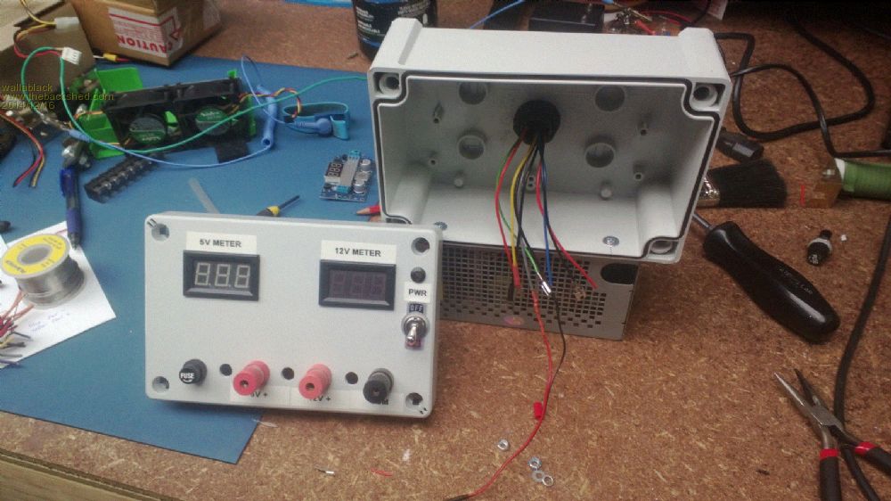
If anyone has a decent schematic or "how to" to use a pot etc to make the 12v and 5V adjustable please let me know...Dr. Google is good but also confusing lol. Foolproof systems do not take into account the ingenuity of fools. |
||||
| davef Guru Joined: 14/05/2006 Location: New ZealandPosts: 499 |
I think there is some important information missing. For 50A what voltage do they expect across the external shunt? 100mV is common and Jaycar may have something. Don't see why is it limited to 50A, maybe that what the readout is set up for. You can't do anything about the voltage ranges, as 5 and 12V are within the current voltage range. You could add a DC amplifier to make 5V put out 50V to increase resolution. But, that would be not be an easy task. Do you need more than 0.1V resolution? |
||||
wallablack Senior Member Joined: 10/08/2011 Location: AustraliaPosts: 164 |
God I wouldn't be expecting to use anything over 10A...One shunt will measure amperage on the 5V side, the other on the 12V side and the third will measure the variable voltage of 12V to 30V produced from the voltage converter/boost buck thingo. I actually want to do without the voltage regulator circuit board and make the voltage variable with a pot similar to the following one I found. 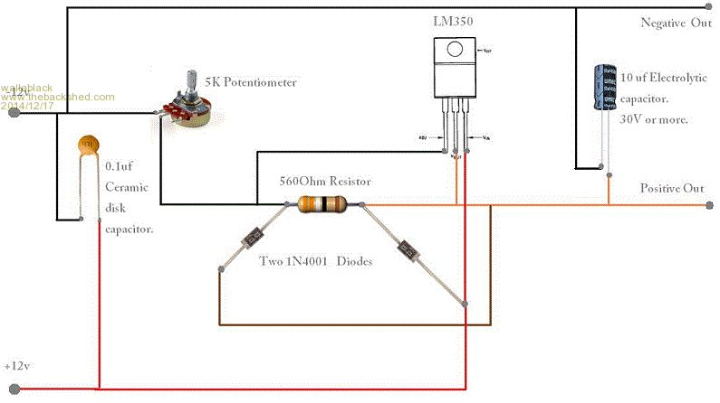
I would imagine the off the shelf ammeter/voltmeter is just at 50A because it "sound" user friendly...who knows. Foolproof systems do not take into account the ingenuity of fools. |
||||
Downwind Guru Joined: 09/09/2009 Location: AustraliaPosts: 2333 |
Personally i think you are going about it the wrong way, where you should build a variable power supply with current limiting, as that way you have some protection to current overloads. Have you looked on the forum and viewed the design i put forward for a power supply here. http://www.thebackshed.com/windmill/articles/VariablePowerSu pply.asp I struggle to see why you need a fixed 5v and 12v supply when a variable supply will do that anyway, if you do want a fixed supply simply add a switch to select 5v, 12v, variable voltage, that way its just a single volt meter and a single current meter. With current limiting you can stuff up and not blow up your power supply. I often end up with a short in a circuit and dont kill my supply due to current limiting, i can clip my DC supply leads together and still not kill the power supply due to current limited. If you do enough with a power supply sooner or later you will short something and kill it if you dont have current limiting, then its back to square one with rebuilding it.........been there done that several times in the past. Pete. Sometimes it just works |
||||
| Gordz Regular Member Joined: 10/08/2013 Location: AustraliaPosts: 55 |
IMHO I would stick with the buck boost as it is more efficient being a switching topology. The shunt for your ammeter would depend on the designer of the unit. If it measures up to 50A max then it will likely be around 0.1 ohms or so, I would email the supplier and ask. If you do want to build a simple V regulator perhaps the LM338K will do as this will give you 3 to 5 amps. Either way I agree with Guru that no current limiting is a recipe for disaster especially when you are using an ATX power supply ad the bulk source. |
||||
Grogster Admin Group Joined: 31/12/2012 Location: New ZealandPosts: 9308 |
I thought that PC PSU's already have built-in short-circuit and overload protection, do they not? ...perhaps not..... Smoke makes things work. When the smoke gets out, it stops! |
||||
| VK2MCT Senior Member Joined: 30/03/2012 Location: AustraliaPosts: 120 |
Yes PC supplies usually have protection of different sorts. Bear in mind that 5v could provide at least 25amps and 12v at least 10amps approx. So the load may become crispy very quickly. I use a PC supply at times when lots of current is needed, but purchased a commercial supply because the current limit can be preset. This helps me from unnecessarily creating expensive brown smoke. The supply can also source more than 12v when occasionally needed. John B VK2MCT |
||||
Grogster Admin Group Joined: 31/12/2012 Location: New ZealandPosts: 9308 |
Yes, that makes sense. Overload short-circuit kind of protection, but it would/could happily supply 20-amps or so into a load(read: fault!) without shutting down. Understood. Meanwhile, in silicon heaven..... Smoke makes things work. When the smoke gets out, it stops! |
||||
Downwind Guru Joined: 09/09/2009 Location: AustraliaPosts: 2333 |
I think some of you have missed the point of current limiting, as why wait for a huge current overload to trip a shutdown on the supply PSU. The view of a built in current limit to the PSU to protect the circuit is just asking for release of the magic smoke from a circuit. With a controlled power supply you have some control to current limited supply, and not just a arc welder at 25 amps plus blasted into a circuit. Pete. Sometimes it just works |
||||
Grogster Admin Group Joined: 31/12/2012 Location: New ZealandPosts: 9308 |
Yes, good point. I also would be inclined to spend the cash, and get a proper lab PSU with full adjustable current limiting. PC PSU can deliver some serious current, but as has been pointed out, with overload current-limiting only. I did see a video on YouTube a while back where a guy used a PC PSU and a heap of polyfuses via a switch to preselect various current limits. I guess that worked OK, but was probably a bit crude compared to the accurate current limit you can get on a proper adjustable lab PSU. With even these PSU's now going to switchmode, you can get some very juicy lab PSU's that are fully adjustable, yet much, much lighter then the older transformer based units, so they are nowhere near as expensive as the big and heavy high-current lab PSU's that used to be about. Smoke makes things work. When the smoke gets out, it stops! |
||||
Grogster Admin Group Joined: 31/12/2012 Location: New ZealandPosts: 9308 |
I know you already have your LED modules etc, but I found this on ebay. 0-32v adjustable output voltage, 0-8A adjustable current limit - US$25 with free freight. Because I am something of a sucker myself, I have bought one of these to play with. While I won't be feeding it with an ATX supply, I will feed my test module with a 15v or 18v laptop PSU, as these can be had in 5A current flavours very cheaply. Smoke makes things work. When the smoke gets out, it stops! |
||||
wallablack Senior Member Joined: 10/08/2011 Location: AustraliaPosts: 164 |
Looks like I am a bigger sucker than you lol...I just bought 2....always want a spare cos I'll probably blow one apart playing... Foolproof systems do not take into account the ingenuity of fools. |
||||
Eugeneo Newbie Joined: 12/04/2015 Location: CanadaPosts: 20 |
In case anyone is interested - The Corsair 550 watt non-modular version has a TL431 on the output side before the optical isolation feedback and can be converted to a variable voltage supply with a single pot and resistor from 3.5 to 15V (careful of the cap rating). You can put an shunt op-amp to feed back and get a switch mode regulated current supply as well. I suspect all the newer power supplies use this type of circuit and can be converted. Careful - if you decide to disable the current limiter, the thing can supply a few hundred amps and surprisingly not crater. My local computer store had these on a blow out sale for like $30 so I bought 4 of them and now I have a 50V - 50A continuous variable supply. Let me know if anyone is interested and I can dig up the mods. |
||||
Downwind Guru Joined: 09/09/2009 Location: AustraliaPosts: 2333 |
Hi, I am very interested, so if you can dig out the mods it would be great. There has been a few threads years back on modding PSU to variable supplies but was not as simple as you have suggested. Look forward to knowing more detail about the mod. For example i can buy a new PSU as listed below, although im sure i have an old one here somewhere. Pete. Sometimes it just works |
||||
Eugeneo Newbie Joined: 12/04/2015 Location: CanadaPosts: 20 |
Hi Pete, I'll dig up the photos and post them up when I get a chance. The particular model would probably be a couple years old now but I will get a model number just in case they have it for sale. I can only assume that the other Corsair supplies would all use the same type of topology for the feedback circuit. Basically it's really simple. you will need to find the TL431. It's a TO-92 package with three terminals. The Anode was connected to the ground. The Cathode is connected to a resistor then to the input side of a optical isolator (4 pin dip). The reference is connected to a 2 resistor divider. All you have to do is put the pot and resistor between the high side of the 2 resistor divider and you have voltage control. I used a 50K ohm pot with an inline 10K resistor. To make sure you are soldering the connections in the right place, you can measure the reference to Anode and it should be very close to 2.5V WARNING: Be VERY careful when you do this. The high side DC voltage can be 170 to 400 VDC depending on what your AC input is. There's a stand-up module that controls the PWM to the fan based on temperature and current load / overcurrent trip / power on input (green wire). You need to disable the overcurrent trip by cutting the trace. I'll try to post the rest soon. Later, |
||||
Downwind Guru Joined: 09/09/2009 Location: AustraliaPosts: 2333 |
Eugeneo, Thanks for the reply, it do sound rather simple to make the mod. Im not your average beginner in electronics, but there is others that my follow your information so you do need to cover all bases. i look forward to more detailed info, as i can see a huge use for cheap power supplies, for example increasing the voltage on my CNC mill. Pete. Sometimes it just works |
||||
Eugeneo Newbie Joined: 12/04/2015 Location: CanadaPosts: 20 |
Wow, I don't remember it being this complicated! Completion 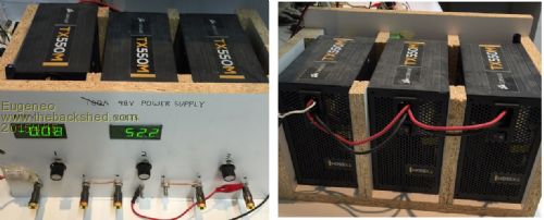
PCB 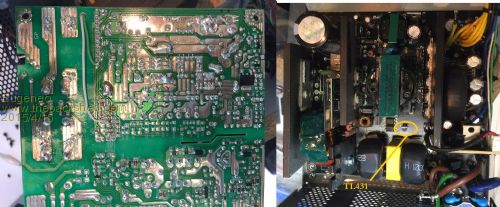
Bring out a Green wire 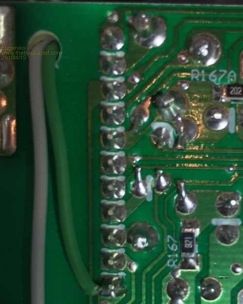
Bring out a White wire 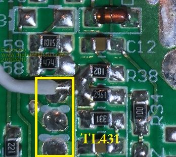
Bring out a Black wire from any ground Bring out a Red wire from the +12 volt rail 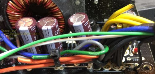
Solder these if you want the over current protection disabled (optional) 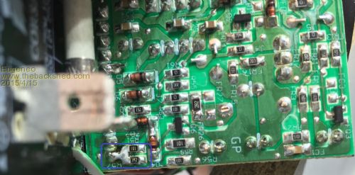
The connections to the pot. These resistors values will give you about 3.5V to 15V output 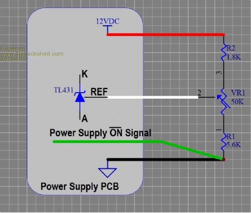
Use this circuit if you want to current limit using VR2 from 1.48A to 50A 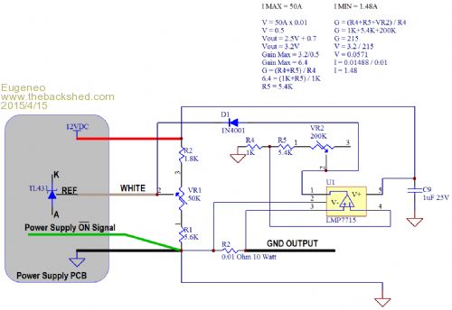
Good luck! |
||||
Downwind Guru Joined: 09/09/2009 Location: AustraliaPosts: 2333 |
Hi Eugeneo, All looks rather simple, and if i can find the right PSU here i will have a go at the mod. Thanks for the info thus far. Pete. Sometimes it just works |
||||
Eugeneo Newbie Joined: 12/04/2015 Location: CanadaPosts: 20 |
Hi Pete, You're welcome, this was a fun one. Let me know how you make out and give me a shout if you run into any problems. |
||||