|

|
Forum Index : Electronics : charge controller
| Author | Message | ||||
| irishron40 Senior Member Joined: 22/09/2014 Location: IrelandPosts: 251 |
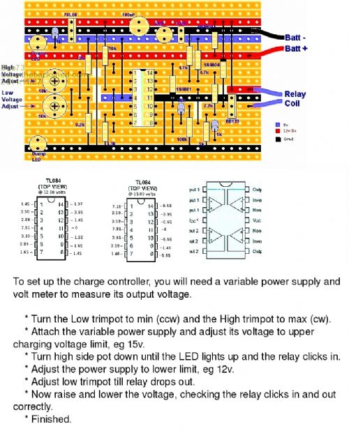
http://www.thebackshed.com/windmill/articles/TL084-Controlle r.asp Hi all. I'm after building charge controller at above link adres. When I connect 12 volt I hear the relay kick in , but both led,s light up. And when I turn trimpots nothing happens. My relay is 5 pin I thought Pin 30 is gonna be connected to positive feed from turbine. Pin 87 to positive dunpload Pin 87a to battery plus And the 2 dumpload wires on the veroboard to 85 and 86. What am I doing wrong? Than yo Ron . |
||||
| Bub73 Senior Member Joined: 10/12/2009 Location: United StatesPosts: 116 |
Hi irishron40 ; Maybe this pic will help and do a forum search there is a lot of info on it back a ways. Bob 
|
||||
| irishron40 Senior Member Joined: 22/09/2014 Location: IrelandPosts: 251 |
I tried that and followed the instructions.its hard to see where and which cablesbgo where on relay. The moment I connect power the relay clicks , and both the red and green led come on. But no responce from trimpots.I'm sure the veroboard layout is correct. So wonder how to wire relay .and variable power supply. Thank you |
||||
| rustyrod Senior Member Joined: 08/11/2014 Location: AustraliaPosts: 121 |
Looking at the circuit BD139 is the switch that turns on your relay. As you have the "click" BD139 is already on. What voltage are you feeding it with? If you are too high it will go into DUMP mode like it is supposed to do. Try 11 volts, if relay still clicks then - If your ic is in a socket simply unplug it and retest, if the relay still clicks there is a problem with BD139. Could it be in back to front ? If your ic is soldered direct, - unsolder one end of resistor 2.2k between pin 14 and the base connection of BD139. This should turn it OFF if not suspect BD139. The wiring on the relay pins 30/87/87a should have no bearing on the relay being energised. in fact if you are concerned disconnect them at this stage. Your description of the wiring is correct. If the relay does not click with the ic removed then more detailed search around the ic will be needed. I will study the circuit while you do these tests. We will go on from these results. Always Thinking |
||||
| irishron40 Senior Member Joined: 22/09/2014 Location: IrelandPosts: 251 |
When connecting power the green led is on.when adjust high trimpots redcled also lights up.there is a rattle in relays like she vibrates.when I tap on relay it seems to disapear. So think its a faulty relay.thank you for your reply as this is my first ever project. |
||||
| Bub73 Senior Member Joined: 10/12/2009 Location: United StatesPosts: 116 |
To set up the charge controller, you will need a variable power supply and volt meter to measure its output voltage. Some photos of the board top and bottom may help also. Bob |
||||
| rustyrod Senior Member Joined: 08/11/2014 Location: AustraliaPosts: 121 |
In the photo "My finished Controlor" It appears the left most RED wire from the terminal strip is the Battery input and the wire appears to go to the 87a terminal over the top of the wire from the centre of the terminal strip. The relays I have met would have the 30 terminal blade made vertical toward the rear. So from my observation/experience, of the photo the wiring is incorrect in that photo. Always Thinking |
||||
| Bub73 Senior Member Joined: 10/12/2009 Location: United StatesPosts: 116 |
Its the two blue wires in the photo that control the opening and closing of the relay. They must be across the relays coil so the B139 can switch. the ground side on and off. The other relay pins will vary from relay to relay, you just have figure that out so your load is switched on an off when you want it to. Bob |
||||
| irishron40 Senior Member Joined: 22/09/2014 Location: IrelandPosts: 251 |
Thank you all for the replies. 
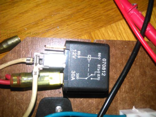
This is my relay. Thank you |
||||
| irishron40 Senior Member Joined: 22/09/2014 Location: IrelandPosts: 251 |
Could someone confirm which pins should be connected to positive turbine(+) and which onbto battery , dumpload and switch wires from veroboard? Thanks. |
||||
| Gizmo Admin Group Joined: 05/06/2004 Location: AustraliaPosts: 5078 |
Pins 85 and 86 go to the relay output of the veroboard, doesn't matter which way round you connect them. With your variable power supply, you will hear the relay click in and out as you adjust your supply voltage up and down. The you can worry about connecting up the relay contacts. Pin 87a goes to the battery + Pin 87 goes to the dump load Pin 30 goes to the windmill output. Glenn The best time to plant a tree was twenty years ago, the second best time is right now. JAQ |
||||
| irishron40 Senior Member Joined: 22/09/2014 Location: IrelandPosts: 251 |
Thats working Glenn.the only thing I figured is that the positive wire from vero board has to be connected to pin 30 also. I only have one confusion.when I connect variable supply to battery, and I set it below 12 volts the relay rattles.so if there is no wind power supply and my battery power goes below low setting it rattles. Why would that be? Thank you |
||||
| irishron40 Senior Member Joined: 22/09/2014 Location: IrelandPosts: 251 |
just wonder one thing. vero board had the 2 pot meters to set high and low battery voltage. when battery reaches lets say 15 volt the relay swithes to dumpload. but my understanding is that if pin30 ( turbine) is connected to pin 87 ( battery) veroboard is connected to battery also on pin 87 now my question. turbine is connected to battery by pin 30 and battery pin87 if turbine creates 15 or more volt, wouldnt that then not trigger veroboard to switch relay to dump? eventho my battery itself isnt full? ron |
||||