| Author |
Message |
Rubes
Newbie

Joined: 01/05/2009
Location: Posts: 36 |
| Posted: 07:37pm 12 Nov 2014 |
 Copy link to clipboard Copy link to clipboard |
 Print this post |
|
Hi all
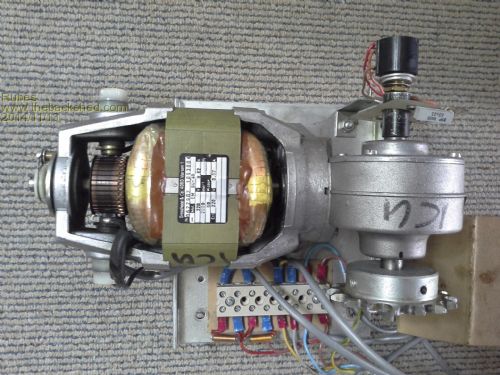
Wondering if anyone would have an idea of how to wire up this salvaged motor, it has 2 wires to the brushes via a small transformer and two to the windings of the stator. other wires go to a rotary encoder. Rotor coils seem ok by resistance test.I am only interested in running this in one direction and at a constant speed. Detail Plate reads Groschoop & Co 4060 Viersen 1, 220v, 0.62A, 2000min-1, 80 Wcosp. Can't find any info on the net
I don,t usually mess with 220v AC but need this motor for a project


|
| |
Pete Locke
Senior Member

Joined: 26/06/2013
Location: New ZealandPosts: 181 |
| Posted: 08:11pm 12 Nov 2014 |
 Copy link to clipboard Copy link to clipboard |
 Print this post |
|
Assuming (now that's a bad phrase for a start :-) it was from a devise that did go in both directions, the field and armature windings will be terminated separately. The field is normally in series with the armature. Direction is changed by reversing the field windings. Start with the armature and field windings in series as is the norm' and see how that works for you. Oh. don't touch the red wire (brown, white or black depending on your country) coz that's the one that bites. Also, the 'small transformers' you mention are chokes, used for a bit of AC noise suppression. Good luck.
Cheers
Pete'.Edited by Pete Locke 2014-11-14 |
| |
Rubes
Newbie

Joined: 01/05/2009
Location: Posts: 36 |
| Posted: 12:35pm 13 Nov 2014 |
 Copy link to clipboard Copy link to clipboard |
 Print this post |
|
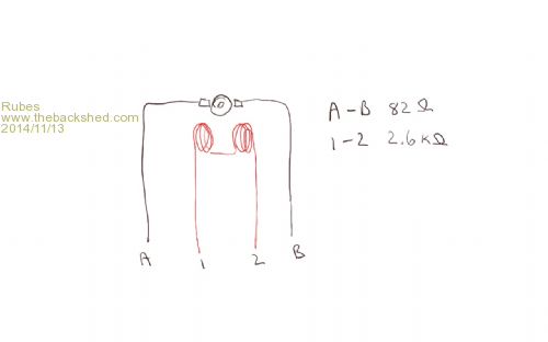
Thanks for the reply Pete. Just traced the wiring by continuity and the 2 fields are in series as is the armature which makes it impossible to go field1-armature1-field2-armature2? am I right? see sketch of circuit as it stands. Only way would be field 1-field2-armature1-armature2 unless I am getting it wrong completly. Thanks Cheers
Oh and you really covered all the colours to avoid

|
| |
rustyrod

Senior Member

Joined: 08/11/2014
Location: AustraliaPosts: 121 |
| Posted: 07:49pm 13 Nov 2014 |
 Copy link to clipboard Copy link to clipboard |
 Print this post |
|
If it were mine I'd power in A & 1 and join 2 & B.
if it rotates wrong way power in A & 2 join 1 & B
because it has commutator and brushes it will run on DCEdited by rustyrod 2014-11-15
Always Thinking |
| |
Tinker

Guru

Joined: 07/11/2007
Location: AustraliaPosts: 1904 |
| Posted: 12:11am 14 Nov 2014 |
 Copy link to clipboard Copy link to clipboard |
 Print this post |
|
Rubes, what you show as *two* fields is considered ONE winding. It has to be arranged that way to create a N & S pole (alternating) between them.
Please consider the advice above (joining A&1 + 2&B as a BAD idea. While this *might* work on low voltage DC - putting the full mains voltage across the 82 ohm armature is just asking for the magic smoke to come out.
Klaus |
| |
rustyrod

Senior Member

Joined: 08/11/2014
Location: AustraliaPosts: 121 |
| Posted: 01:47am 14 Nov 2014 |
 Copy link to clipboard Copy link to clipboard |
 Print this post |
|
Power in Active to A
Neutral to 1
and join 2 with B exactly the same as any electric drill/angle grinder.
I am sorry I did not make myself clearer. 
Disclaimer. All Australian power work over the voltage of 32 volts is illegal unless done by a qualified sparky. yes 48 volts is included in the rule 
I don't fix em just pull em to bits.
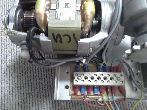
photo looks like (I say looks like, need underside photo) from left
- terminals 1 and 3 are to the brushes
- terminals 5 and 6 are the fields
-- the yellow and ? blue twin wires would not be needed
remove the chokes and all other wiring on this side of terminal strip
the chokes hanging out like that are waiting to bite you 
perhaps active in terminal one
neutral in terminal 6
join terminals 3 and 5
IMPORTANT screw a good earth to the frame of the motor
if it runs the gnorw way swap the black field wires in 5 and 6
IF you need to use all those other wires for what you are doing you are on your own.Edited by rustyrod 2014-11-15
Always Thinking |
| |
Rubes
Newbie

Joined: 01/05/2009
Location: Posts: 36 |
| Posted: 01:59am 14 Nov 2014 |
 Copy link to clipboard Copy link to clipboard |
 Print this post |
|
Thanks guys I will give it a go in the morning, anyone notice what is written on the motor with a marker pen (its upside down) lolEdited by Rubes 2014-11-15 |
| |
solarwind

Regular Member

Joined: 03/02/2008
Location: South AfricaPosts: 51 |
| Posted: 08:26am 14 Nov 2014 |
 Copy link to clipboard Copy link to clipboard |
 Print this post |
|
If you have access to a "variac" or similar variable ac autotransformer, you could connect the motor as suggested and feed it via the "variac" starting at a low voltage. If it starts to run, gradually increase the voltage by turning the "variac" and see what happens. It would be wise to include a 1/2A to 1A fuse and an Ammeter in line. If there is a fault in the motor, the ammeter will tell you in advance. You know what full-load amps should be (0.62A). It should not even come close to this (unloaded) while you crank up the "variac".
You don't have success until you've tried it! |
| |
Rubes
Newbie

Joined: 01/05/2009
Location: Posts: 36 |
| Posted: 05:49pm 14 Nov 2014 |
 Copy link to clipboard Copy link to clipboard |
 Print this post |
|
Hooked it up this morning as per Rustyrods suggestion, First tried DC starting at 12V and working up to 50 then on to 220 AC ,nothing, not even any smoke, bit disappointing actually.
Anyhow after some more reading it seems the windings should not have a resistance value of anywhere near 2.7k so I guess the motor is dead, I hope to somehow use the gearing mechanism.
I have learned a fair bit from this exercise so not in vain and thank you to all who took the time to respond.  Edited by Rubes 2014-11-16 Edited by Rubes 2014-11-16 |
| |
rustyrod

Senior Member

Joined: 08/11/2014
Location: AustraliaPosts: 121 |
| Posted: 11:23pm 14 Nov 2014 |
 Copy link to clipboard Copy link to clipboard |
 Print this post |
|
In some fans and transformers the manufactures put/sneak a small black heat sensitive device under the insulation wrapping, it is usually about 4/5 mm square and 2mm thick, and damm hard to find.
In fans it is wired between the two field winding if you find one of these sneaky things just ease it up enough to twist it around enough to short it out of the circuit.
The fan will continue to work, haven,t had any smoke yet.
Was the sensor too sensitive? Or not allowance for global warming?
With your motor, - test to find out which field coil has a higher resistance than the other. by pass it.
Wire a 100 watt 240v bulb or flood light (not cfl's) into one wire of your power lead
If there is a serious problem the light will be full brightness.
What I mean is connect, say active to one side of the bulb and the other side to the motor and then other side of the motor to neutral to complete the circuit.
If the motor runs too slow try a bit higher wattage bulb.
It may get the motor to run, but when you drive something it will probably get slower and slower as the load increases until it stops and then light will be almost full brilliance. Then you can throw it in the bin, now you know exactly what was faulty.
A "variac" would be ideal.
One of those safety pack extension units is a handy thing to have in your back shed if you must poke around with elec-trick-ety!
.62 amps multiplied by 240 equals 148.8 watts, so a 150 watt flood light and a good motor would be both at half brightness/speed. Theoretically.
If you had had a really big motor use a bar heater.
Not me, but my Dad had a board with switches on it so he could turn on more and more lights, OR all the way up to an old clothes iron.
Some Televisions had no transformers and ran straight off the main power. They had only the two wires ( both black) and one went to the chassis.
There were no such things as safety switches in his day. So He reasoned he would rather light up a bulb with his body rather than get a 15a fuse wire to blow.
And can you believe we wore ties to work with metal threads, a glistening, woven into the fabric. We looked smart, "cool" hadn't been invented.
Familiarity with power is when "ZAP" happens, Check CHECK check the plug is not plugged in. Forget the switch. UNPLUG it and SEE the plug on the floor I say SEE the plug on the floor. did you check? obsessive-compulsive here is acceptable.
Edited by rustyrod 2014-11-16
Always Thinking |
| |

