| Author |
Message |
Pete Locke
Senior Member

Joined: 26/06/2013
Location: New ZealandPosts: 181 |
| Posted: 11:39pm 11 Aug 2013 |
 Copy link to clipboard Copy link to clipboard |
 Print this post |
|

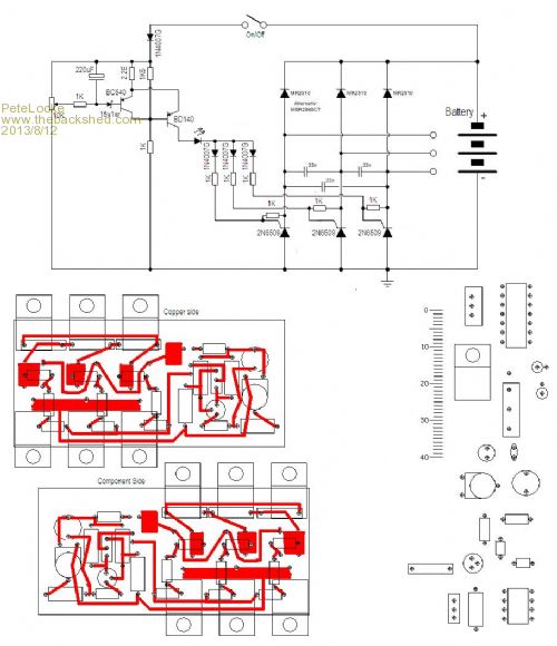
If anyone is interested in an easy and fairly hardy 3 phase regulator, this one works very well. Components are set for a 24 volt system and based on the Rotax diagram found on the net, with the mistakes corrected and all the un necessary bits taken out. The SCR's and diodes are mounted under the PC board and screwed to the heatsink. This supports the board. The PC layout is included, and the ruller is in mm if you want to copy it.
Cheers
Pete'.
http://smg.photobucket.com/user/Meatter/media/PCB_zpsea31aef 7.png.html?sort=3&o=0
This has a clearer view.Edited by Pete Locke 2013-08-13 |
| |
BobD

Guru

Joined: 07/12/2011
Location: AustraliaPosts: 935 |
| Posted: 12:22am 12 Aug 2013 |
 Copy link to clipboard Copy link to clipboard |
 Print this post |
|
Pete
Your link has a problem
Bob

|
| |
brucedownunder2
Guru

Joined: 14/09/2005
Location: AustraliaPosts: 1548 |
| Posted: 02:19am 12 Aug 2013 |
 Copy link to clipboard Copy link to clipboard |
 Print this post |
|
Hi Peter,
can it be modified for 48v 3/phase ?
I'd be interested in either the kit or completed board ,no box .. money up front.
Thanks ,
Bruce
Bushboy |
| |
Downwind

Guru

Joined: 09/09/2009
Location: AustraliaPosts: 2333 |
| Posted: 07:08am 12 Aug 2013 |
 Copy link to clipboard Copy link to clipboard |
 Print this post |
|
Im still trying to work out why you would want a 3 phase voltage regulator in the first place.
And secondly what diverts the power when the regulator switches the SCR's off.
To me it looks like a good design to allow the mill to runaway.
Personally i think just working with DC after a rectifier is far better than a 3 phase switching rectifier that can leave the mill not connected to anything.
My rule is the mill MUST always be connected to something, so if a failure in electronics occure there will always remain a loading on the mill.
The simplest way to do this is a solid connection to the batteries,(no switches, no fuses, no relays) and divert the power elsewhere for voltage control.
The worst that can happen with a fault is the batteries get a little overcharged and gassed some, and far better than a runaway mill.
If Peters circuit was used as a 3 phase dumpload voltage controller, then it could be a lot safer and a better method.
This would mean a normal 3 phase rectifier between mill and batteries, and the voltage controller switching the 3 phase to a dumpload to regulate voltage.
Pete.
Sometimes it just works |
| |
Pete Locke
Senior Member

Joined: 26/06/2013
Location: New ZealandPosts: 181 |
| Posted: 09:24pm 12 Aug 2013 |
 Copy link to clipboard Copy link to clipboard |
 Print this post |
|
Don't you love free picture hosting sites. Photobucket was never this hard to deal with  . If you change the smg.photobucket etc to img.photobucket it seems to work. Sorry about that. . If you change the smg.photobucket etc to img.photobucket it seems to work. Sorry about that.
Hi Bruce.
Sorry I don't do kit sets or made up projects. I tinker in the shed and develop or modify existing items for a specific purpose. The information I then hand out free to anyone who wants to either use it as is or change for a specific purpose of their own. The information is yours to use if you wish, but will need to find an electronics hobby person to knock one up. It's not a hard item to build and I wish you luck in finding a use for it.
Hi Pete
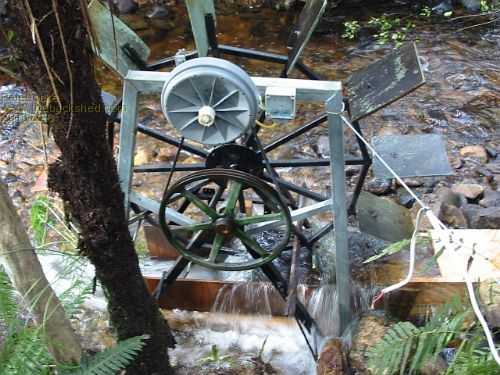
You are of course right in it's not suitable for a windmill. This was put together as a replacement for a mate of mine who has a waterwheel. Constant rev's from the thing and a 2x7c smart drive to work at about 350 rpm. Apologies for not putting that in the original post. This is only stage 1 of development. We are practising on his diesel generator batteries. If this all is happy and doesn't let the smoke out then further use of his stream will be investigated.
Cheers
Pete'
P.S
Aw crap. The img change in the link to a better picture seems to work, but you have to try it twice. I've sent a query to Photobucket (have used this copy link thing often in the past with the model planes with no problem) but still waiting for a response. Edited by Pete Locke 2013-08-14 |
| |
Downwind

Guru

Joined: 09/09/2009
Location: AustraliaPosts: 2333 |
| Posted: 11:28pm 12 Aug 2013 |
 Copy link to clipboard Copy link to clipboard |
 Print this post |
|
Peter,
It can be used with a windmill and may work very well as a dump voltage controller, i am tempted to knock one up and try it, because it might allow some form of PWM charge control, and allow low current charging where the mill would be fully diverted to a dumpload.
I suspect your regulator might function a bit like a car alternator reg, where it will cut in and out constantly at close to full charge, giving small charge boosts to the battery.
The difference being a car reg switches off the field windings to stop charging, and for a windmill the power is diverted to a resistive load.
Can you explain the sensing circuit operation prior to the SCR's, and how 24v was set, Im too lasy to work it out when you already have.
Pete.
Sometimes it just works |
| |
Pete Locke
Senior Member

Joined: 26/06/2013
Location: New ZealandPosts: 181 |
| Posted: 06:21pm 13 Aug 2013 |
 Copy link to clipboard Copy link to clipboard |
 Print this post |
|
Hi Pete.
The regulator is a very simple beast. Just a Schmitt trigger whose on/off state is set by the zenner diode and the 2.2E common emitter resistor. Plenty of info on the net on how these things work. The lower the value of the common emitter resistor, the smaller the gap between switching on & off. The zenner used was a 15v 1watt, but could be anything about that value for 24 volts. Lower if it was used for 12. The variable resistor sets the cut out voltage and was set on the bench feeding it with a 30v transformer. Then plumbed into the smart drive stator to check. Yes it does wobble once the set voltage is reached, but that is normal for this type of regulator. The 24v values were easy to calculate. I just doubled the resistor values used for 12 volts, except for the 2.2E common emitter. If you wanted to use it as a dump switch (turning on rather than off once the set voltage has been reached) simply adding another transistor to invert the output of the regulator to the SCR's would be all that's needed.
The only things needed new being the SCR's and the diodes. Both are available from RS Components, with the remainder being ratted from a dead smart drive display module and the junk pile.
http://www.aeroelectric.com/Pictures/Regulators/Rotax-Ducati _Rectifier-Regulator.jpg
The above is the link to the original circuit corrected and modified for this post.
Again this offered to be used or modified by anyone who might have a use for it.
Happy experimenting 
Cheers
Pete'. |
| |
solarwind

Regular Member

Joined: 03/02/2008
Location: South AfricaPosts: 51 |
| Posted: 10:43am 25 Aug 2013 |
 Copy link to clipboard Copy link to clipboard |
 Print this post |
|
Hi Pete,
Thanks for sharing! Many possibilities, one being a regulator for an off-road motorcycle. I once opened one from a motorcycle and "reverse-engineered" (copied the circuit carefully) it and it is VERY similar to your circuit.
You don't have success until you've tried it! |
| |
Pete Locke
Senior Member

Joined: 26/06/2013
Location: New ZealandPosts: 181 |
| Posted: 09:18pm 25 Aug 2013 |
 Copy link to clipboard Copy link to clipboard |
 Print this post |
|
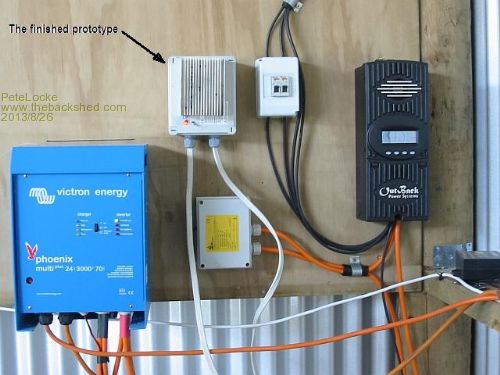
It was a very complex bit of gear before I gave the unnecessary bits a hair cut. Quite a few extra bits in it just to drive a charging lamp. Plus the original circuit as found on the net had errors in it. The one listed has now been connected to a waterwheel set up for a couple of weeks, and so far nothing has let the smoke out. Hope you can make use of it 
Cheers
Pete'.


|
| |

