
|

|
Forum Index : Electronics : Electric fence energiser
| Author | Message | ||||
| Joblow Regular Member Joined: 05/01/2010 Location: AustraliaPosts: 54 |
Hi all. I need to build an electric fence energizer, there are stacks of circuits on the web, but all seem to be high impedance, which are easy and cheap to build but because of their propensity for producing hot sparks, are blamed for starting many grass fires of which lots of those grew into bigger bush and scrub fires. The energizer circuit I’m looking for is that of a low impedance unit with something like the following specs: 4.5 Joule which can maintain 5000 volts, 3A under low weed pressure if the pulse time, (the time the fence is on) is 0.0003 seconds every 15 seconds. Any advice will be greatly appreciated. The low impedance type is also more humane, it tends to cause an uncomfortable muscle contraction rather than an electric shock. I once took a walk around a country reception centre to cool off one hot steamy night, and just got one leg through the fence when I suddenly found out it was electrified 
The man who never made a mistake never made anything |
||||
oztules Guru Joined: 26/07/2007 Location: AustraliaPosts: 1686 |
Joblow, Having rebuilt 5 fencing units in the last week or two, I have a fair idea of how these things work. Do you want it battery powered or mains powered? Mains powered is very simple.... battery powered is not quite so simple. (for your type, will require a small pwm step up from 12v to 4-500v then essentially the same as the mains one) To get the low impedance style, they then use the 500-600v and charge a bank of capacitors (say 100uf@900vdc rating) and then short these into the primary of a transformer.(big scr or triac... cheaper wins 50A@1000v etc.) I have tested with a simple small mains transformer as the HV generator ... in through the secondary of a 240:24v 40W with evil results. As you can see, it is fairly low impedance secondary (not like a car coil type). Probably best to use a bigger tranny, and rewind the 240v side with consideration for large gaps and paper insulation between layers. The HV will break down the wire insulation in no time otherwise...... so wind a layer, transformer paper, and then next layer with the paper extending 1/8th inch out past the copper each time etc etc. then heavy lacquer or even epoxy to seal it up. They then use high R resistors across the outputs to limit the voltage, and a neon flasher across the output as well. Both serve to lower the output impedance, and place a load on the secondary this helps to limit any HV damage to the tranny. 15 seconds seems a bit long a time period.... but means a smaller pwm requirement to charge the cap bank up. You can control the ummph by changing the cap value you discharge into the tranny. Any way, mains or battery. ..........oztules Village idiot...or... just another hack out of his depth |
||||
| Joblow Regular Member Joined: 05/01/2010 Location: AustraliaPosts: 54 |
Mains powered will fit the bill, the reason I went for such a long pulse rate was that I thought it would still do the job ok (cattle) and the unit would last a lot longer by having a reduced load but maybe I should stick to convention and make it shorter. I have looked out a couple of tranys' but no markings, I will check them out soon, one is about 200mm x 150 x 160 and weighs about 12kg probably circa stone age, but I like old stuff. Joblow The man who never made a mistake never made anything |
||||
Downwind Guru Joined: 09/09/2009 Location: AustraliaPosts: 2333 |
What about a transformer from a microwave or would that be to high of an output. I had a circuit i drew out for a battery operated one i repaired some years back, but unable to put my paws on it in a quick search. Will look a little further. Pete. Sometimes it just works |
||||
| Robb Senior Member Joined: 01/08/2007 Location: AustraliaPosts: 221 |
I'v repaired a good few fence energizers and a microwave transformer makes a good bench test transformer BUT there is no way I'd be letting one outside of the workshop. If it kills someone the argument will be that it was not built to meet any standards and you will carry the blame. I love building stuff but thats one thing I wouldn't for the above reason.  |
||||
oztules Guru Joined: 26/07/2007 Location: AustraliaPosts: 1686 |
A microwave tranny is fine for the laminations. After that it is a matter of a rewind of both the primary and secondary coils. The primary of only a 12v or so winding, and the secondary much the same as the primary was originally, but with attention to the insulating properties of the winding. That means transformer insulation paper between the layers of wire making up the secondary.... even though there will be only about the same turns as the original 240v primary. The difference between the original hv secondary of the microwave and now, is that we are now pulsing it unloaded, with nowhere for the HV electrons to go..... idle electrons at hv potential are just looking to mess with anything available. As a microwave oven tranny secondary with similar HV voltages, it had a load at all times for the current to go through (magnetron), and so no real precautions are taken with the windings. I have a circuit board of a Thunderbird mains fencer in my windows partition somewhere, just have to work out how to transform it into a jpeg or gif from a pcb file. (I had to duplicate the original as it had burned through the board in a few places) It will require a transformer as outlined, and a 50A 1000v SCR and a reasonable stud diode for the back EMF .. and about 1 or 2 x 20uf 900vDC pulse grade capacitors. The rest is piddly stuff, and very little of it. I used 50uf 500vAC motor run caps from rockby again, and they do just as well from the history so far. Operation voltage is around 660vDC... so 500ac X 1.414= 707vdc which is why they work ok I suspect. I use a 1000v 50A stud Triac from Rockby.com.au for $5.00, a SCR of the same rating seems to be over $20.00 It is just a voltage doubler from the mains ac to over 600vdc. It charges the caps up, then discharges them through the scr straight into the transformer primary. The discharge is done from a cunning resistor/cap/diac arrangement acting as a relaxation oscillator.. hardly any parts, but packs a punch. You can test it out using any mains to 24v or near transformer, it just may not last very long due to spark erosion in the secondary (was primary 240v winding). Will try and find it and post it soon. ............oztules Edit: It is interesting that the Gallagher style of fencer here uses very nice epoxy embedded transformer... even for the lv converter pwm tranny (battery type), and I have had a few problems with them expanding and splitting the casings. I would have thought their design was idiot proof.... but no, plenty of transformer failures... the Thunderbird ones I have seen blow their SCR's but never once seen a transformer blown. They use the open paper spaced type I describe above. They seem well lacquered, and survive the salty sea air here well so far. ..... opposite to what I would have expected.  Village idiot...or... just another hack out of his depth |
||||
| Joblow Regular Member Joined: 05/01/2010 Location: AustraliaPosts: 54 |
Lots of good info above guys, I'm collecting bits and pieces as I go along. I now have a 150VA (approx) tranny, 240/24, I will rewind it to suit when I get a circuit, there isn't much room for more bulk on the existing primary though, the paper insulation may make it a bit tight. The man who never made a mistake never made anything |
||||
| mann Newbie Joined: 21/12/2010 Location: Posts: 3 |
so which transformer i used give me detailed info abuit transformer.and what is this joule.how i can vary this joule 4.5 j,3j,2.5j and i want output about 9000v |
||||
| mann Newbie Joined: 21/12/2010 Location: Posts: 3 |
plz any buddy tel me what i do now for 9000v output of energizer |
||||
| mann Newbie Joined: 21/12/2010 Location: Posts: 3 |
which transformer i used for it |
||||
| Gizmo Admin Group Joined: 05/06/2004 Location: AustraliaPosts: 5078 |
Hey Mann, This thread is very old, you might have more luck searching Google. Also try to keep your questions to one post. Glenn The best time to plant a tree was twenty years ago, the second best time is right now. JAQ |
||||
| SSW_squall Senior Member Joined: 20/03/2010 Location: AustraliaPosts: 111 |
Hi I hope everyone is having a good break from the usual grind… Here’s a few photo’s of the solar powered electric fence controller that I’ve built for the wife’s horses… It has a 10W solar panel, a car ignition coil and the controller is based on a PIC16F690 with a software interface that has the following menus: ELECTRIC FENCE ON/OFF POWER LEVEL 1>10 BATTERY VOLTAGE xx.xxV DISPLAY CONTRAST 1>10 The power level menu controls how long(dwell time) the ignition coil charges for and therefore the magnitude of the zap (!) it puts out The coil is connected to the fence via a short length of car ignition cable that has approx 5k Ohm resistance. A $8 plastic storage crate makes the whole rig water resistant and portable, sure it might not last forever but it was a better option than a $120 pelican case 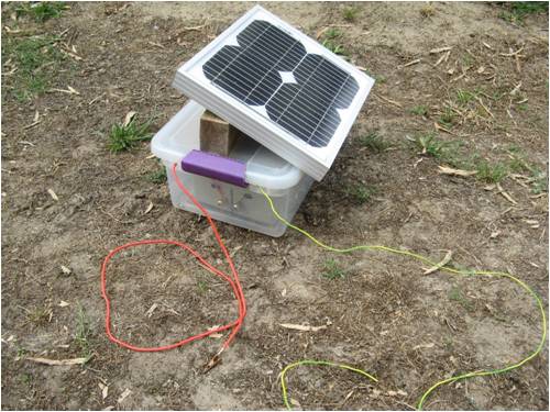
Inside the crate a 7.2Ah SLA battery and the controller with LCD interface. 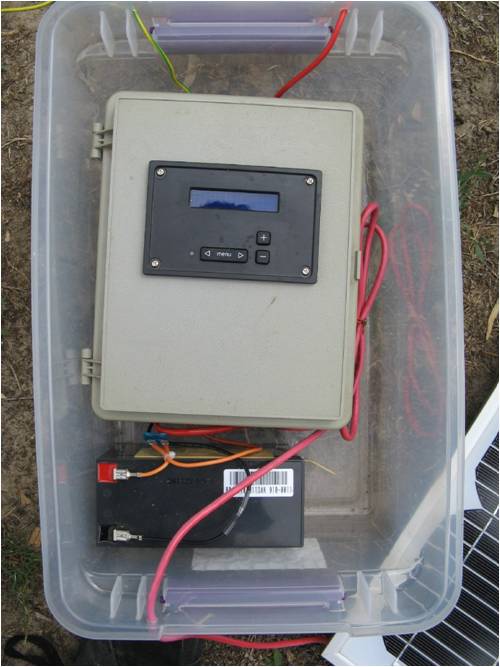
A close up of the screen: 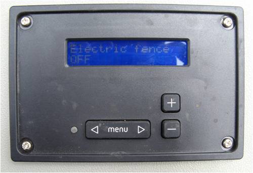
Inside the controller: 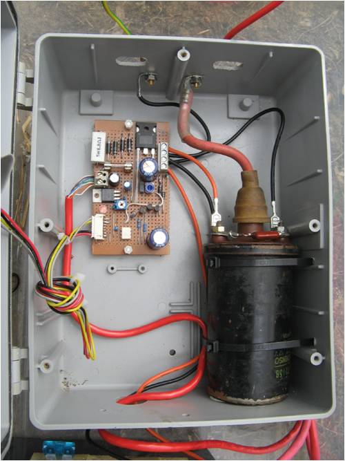
A close up of the circuit board: 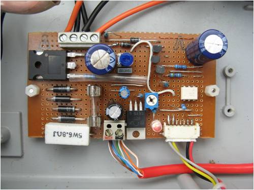
The ignition coil is switched by a very large MOSFET that is snubbed by a string of 75V 5W zener diode and opto isolated for the microcontroller. The coil is separately fused incase something goes wrong. The 10W solar panel charges the battery through a LM317 regulator that limits the voltage to 13.6V (float level) The microcontroller samples the battery and turns off the electric fence if the battery voltage drops below approx 11v, this helps stop the battery from going too flat. The front control panel bears a stiking resemblance to the one found on our powered subs the VOLCANIX and TEKTONIX, hehe!! While this eneded up being an easy wasy for me to put this together, i realize that it may be over complicated for anyone else to make. However the circuit could easily be simplified to use a 555 timer, with a simple pot to vary the power level. I can post the circuit if people want make something similar (JOBLOW) So i won't blab on with enegineering details (flux capacitor ect) here... Given a solar powered thunderbird controller goes for $500, i think we came out ahead 
AB Einstein: Everything should be made as simple as possible, but not one bit simpler |
||||
| survey_sez Newbie Joined: 24/10/2011 Location: United StatesPosts: 1 |
ssw - i hope my reply to this thread is not to late to request your schematic? yes i know this is quite an old thread.. outstanding project! very slick. what not an rc snubber or simply a kickback diode? not sure why the stacked zeners. maybe your schematic will shed some light. i will likely impliment something very similar without the digital interface. great forum all! |
||||
| Kaizen Newbie Joined: 25/10/2011 Location: AustraliaPosts: 1 |
I also just saw this post.... If possible I would also like to request a copy of the schematic! It is very cool!! |
||||
| faburli68 Newbie Joined: 22/02/2013 Location: ItalyPosts: 1 |
very nice!!!please send me copy schematic?possibility? |
||||
muddy0409 Senior Member Joined: 15/06/2011 Location: AustraliaPosts: 125 |
Simplest one of these things I ever saw was a domestic suburban "pet fence". Made in US/Canada or somewhere that used US type mains [lug. Itwas simply a 600V transformer with a series resistor that limited short circuit current to 10mA. No PWM or timer, powered up permanently. This fed an aluminium wire that was stretched around the perimeter fence line at about 10 inches above the ground and 10 inches inside the fenceline. Idea was that if anything (in my case a dog) approached the fence with a plan to dig under it, it would at some time touch the wire while standing on the ground and ZAP! It worked a treat and the dogs only needed to get zapped a couple of times before they accepted the fence was a no-go area. So under normal conditions, no current flow at all, until something bridged the gap between the wire and the ground. I am just about to move to country NSW so I probably will need to make another one for the dogs again. And since the maximum current was limited to 10 mA, I added a pair of reverse connected leds to the box so they would light up should some grass or other rubbish shorted the "live" wire to ground. Don't poo poo conspiracy theories. Remember that everything ever discovered started somewhere as a theory. |
||||
| robot Newbie Joined: 28/01/2015 Location: AustraliaPosts: 2 |
Hi People, Can anyone share their design/experience on a fence energizer using a car ignition coil? Unfortunately SSW_squall has been off-line since 2011 so I haven't been able to raise him to get his circuit. I have a prototype using a coil with a Pixaxe08M2 delivering a 9ms primary winding energising pulse via a power mosfet. The gate has an opto-coupler for isolation although I still have a problem with the picaxe resetting itself despite power line decoupling caps etc, termination of unused pins etc. I'm looking to dissuade our possum population using my wife's veggie patch as the local take-away service. Thanks people. |
||||