Notice. New forum software under development. It's going to miss a few functions and look a bit ugly for a while, but I'm working on it full time now as the old forum was too unstable. Couple days, all good. If you notice any issues, please contact me.
nickskethisniks Guru Joined: 17/10/2017 Location: BelgiumPosts: 477
Posted: 07:03pm 16 Oct 2024
Copy link to clipboard
Print this post
I see there has been some radio silence for a couple of days, so maybe this is a good moment to show my build of an MPPT controller with a Wisemens powerboard running Poida nano firmware, thanks!
This was more of a therapy than just another project. It's difficult to finish projects without starting another one… So I really need to finish this! The goal is 48V nominal with 40A charging for 62V ideal MPPT voltage, passively cooled.
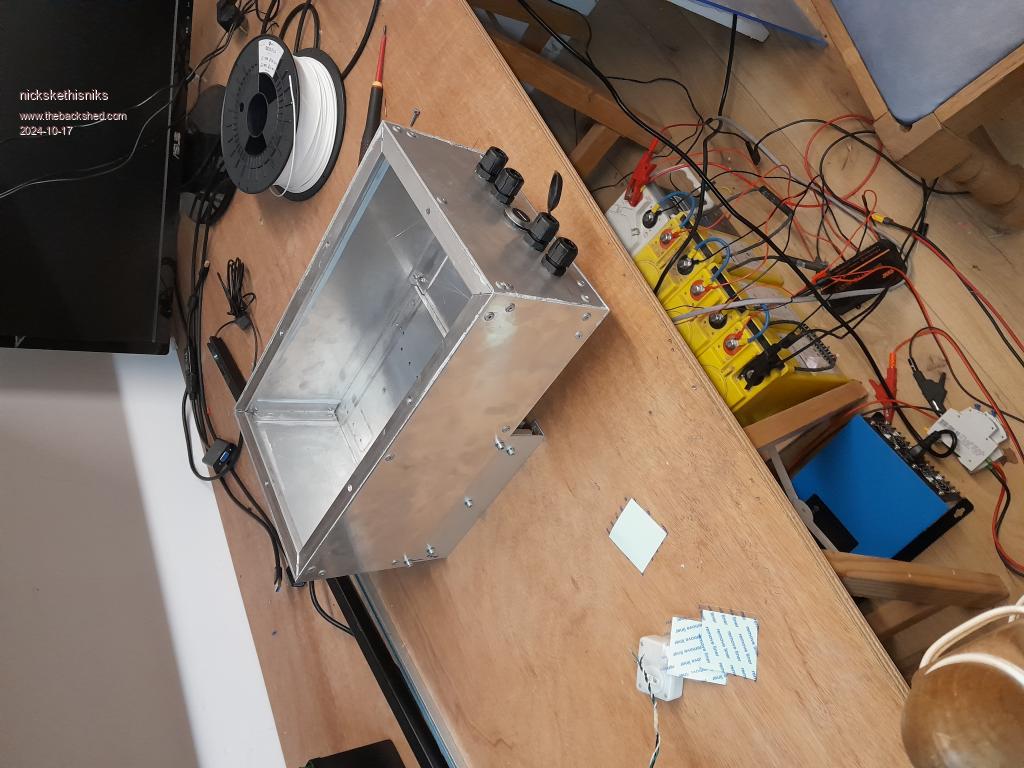
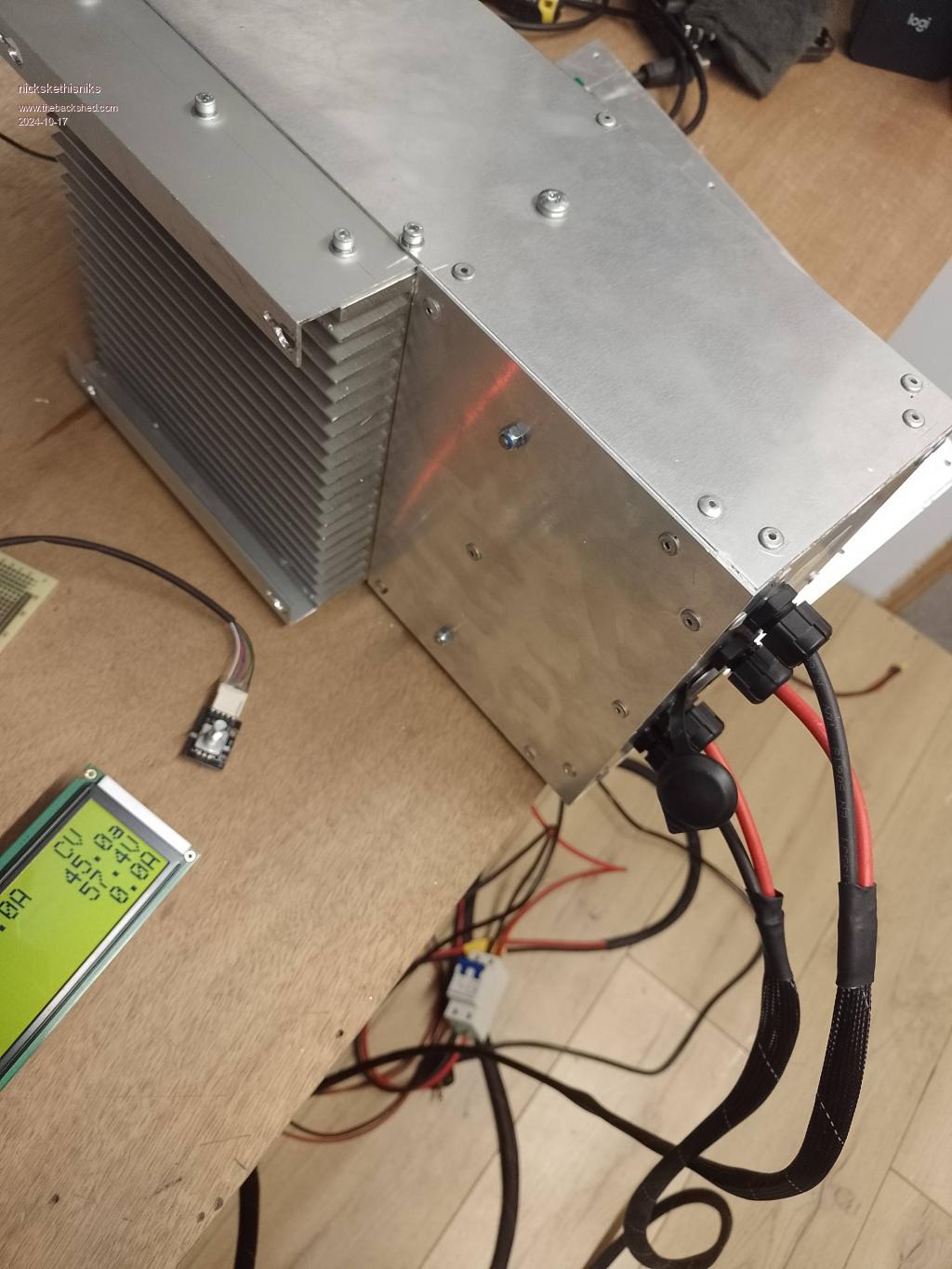
For the casing, I decided to build everything around an aluminum heatsink of about 20x19 cm, perfect for the MPPT controller. I've ordered some aluminum sheets with a thickness of 3mm for the sides and 2mm for the top, and joined everything together with some L-profiles (15x15x2mm) and 4mm rivets. This was not cheap, but a hobby can cost money if and I hate something that just don't fit. The edges don't look great on photo but I also used some silicon before joining the aluminium together. And it's not yet cleaned of.
I actually like the result, and I'm planning to use the same method on something bigger for an inverter. Advice about the subject is appreciated! I wished I could weld aluminium...
It looks big for just a 40A controller compared to chinese devices, but I hope if something goes wrong it is contained within the box. It's also very pleasant when having no size constraints.
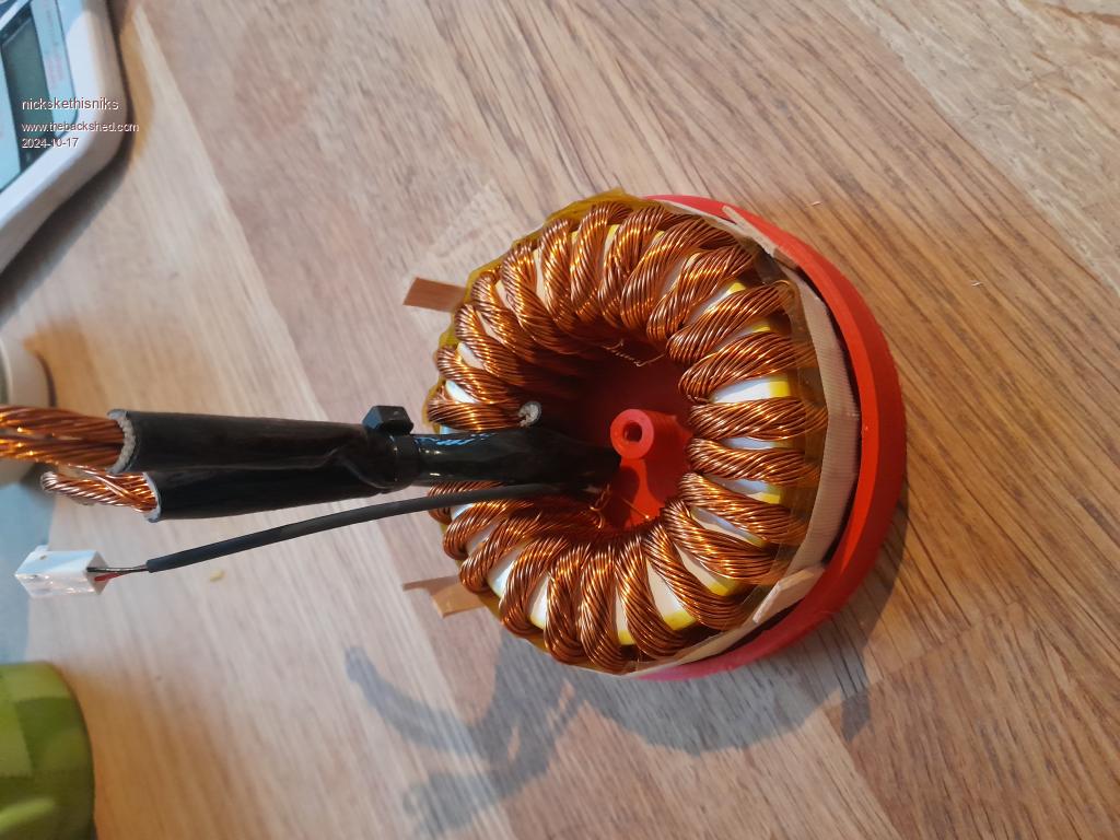
I used 2 IRFP4110 MOSFETs and 2 30CPQ100 diodes, which have proven their reliability in my previous builds. Without ferrite beads, I want to open some discussion about this matter later on. If you use just something without testing you could do harm, but more investigation needs to be done. For the inductor, I used a T300-26D core with 25 turns of 40 parallel 0.56mm diameter wires, which makes it easy to wind. This has 100uH, but when right it drops to 42uH under 30A load . Each wire end of the inductor is split in 2 for easy soldering to a small lug.
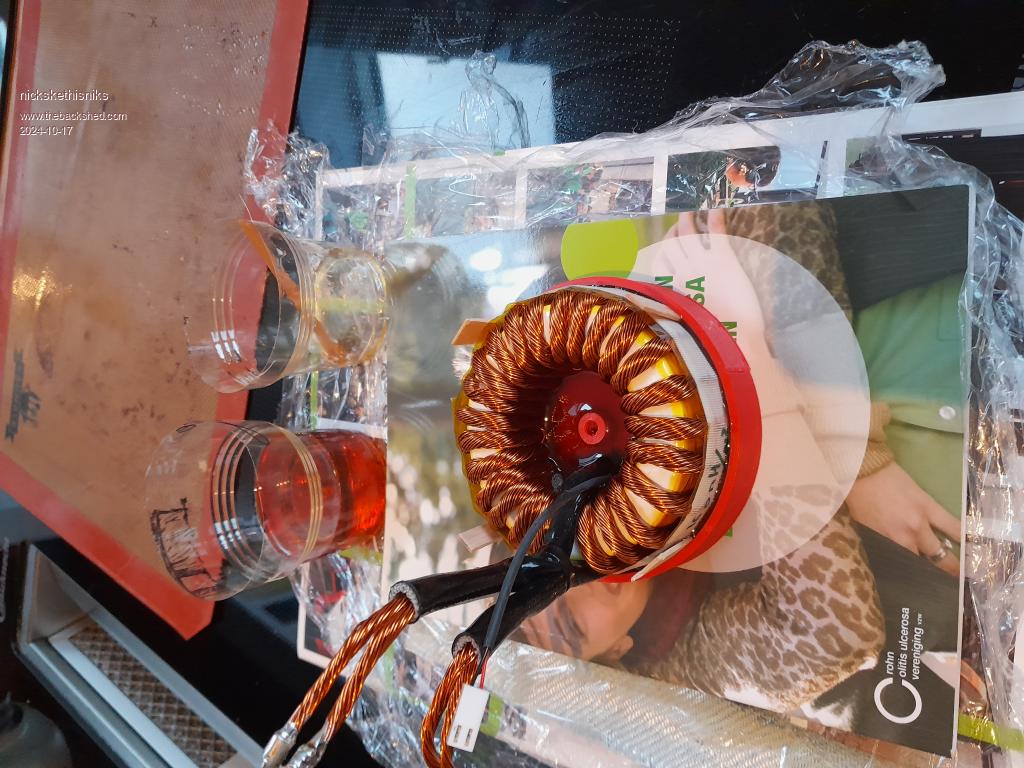
I needed a way to mount it, and I thought I would pot this one in. So, I 3D printed an ABS case and used high-temp (80°C) epoxy. The NTC is also potted in what I found to be the hottest part of the inductor. It went in the oven for 3 hours at 75°C to cure.
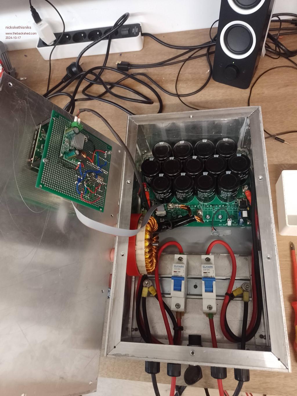
Allthough the position of the inductor next to the flatcable is not ideal I did not have issues so far. The other side could have been a better position. The pwm signal is first buffered with a mosfetdriver and converted to a 12V signal. R1 on the powerboard is swapped with a 1k I think.
I insulated the end of the windings with some glasfiber/silicon sleeves to keep them appart and prevent some potential shorts. It's wound directly on the core without extra tape, did not find good info/papers about the subject yet.
I made a controller board (which I need to make a proper PCB for) on protoboard. It has 2 nanos on 1 print, and a DC-DC converter on the back, which is powered from the battery input.
Before mounting it all in I taped the heatsink with ducktape, for extra isolation
I included a USB socket for easy access to a PC, and some DC circuit breakers, which I need to check to ensure the polarity is correct.
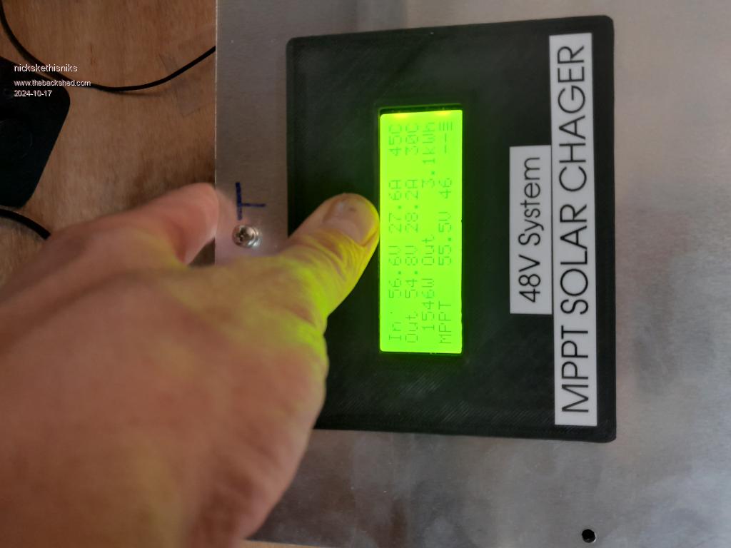
I tested it with a 21°C ambient temperature, flat on the bench, running for 2 hours on a 30A battery charge, but with little voltage difference between input and output. The test stabilized with a 30°C heatsink and a 45°C inductor temperature. It might need a throttling-back function when running in high ambient temperatures, especially if actually run at long 40A continuous intervals. Or go for an inductor core of sendust material and wire with more cross section.
The efficiency was measured in the worsed case was 97.5% wich was with 56.5V in / 47V out at 30A charging amps, measured with clampmeters and voltage measurement on the board to rule out wire losses. Give this some margin please.
Notice, the 3D printed front to hold a plexiglas piece for extra protection, oh I need to press it al little because otherwise it won't show all the pictures... chinese quality hey...
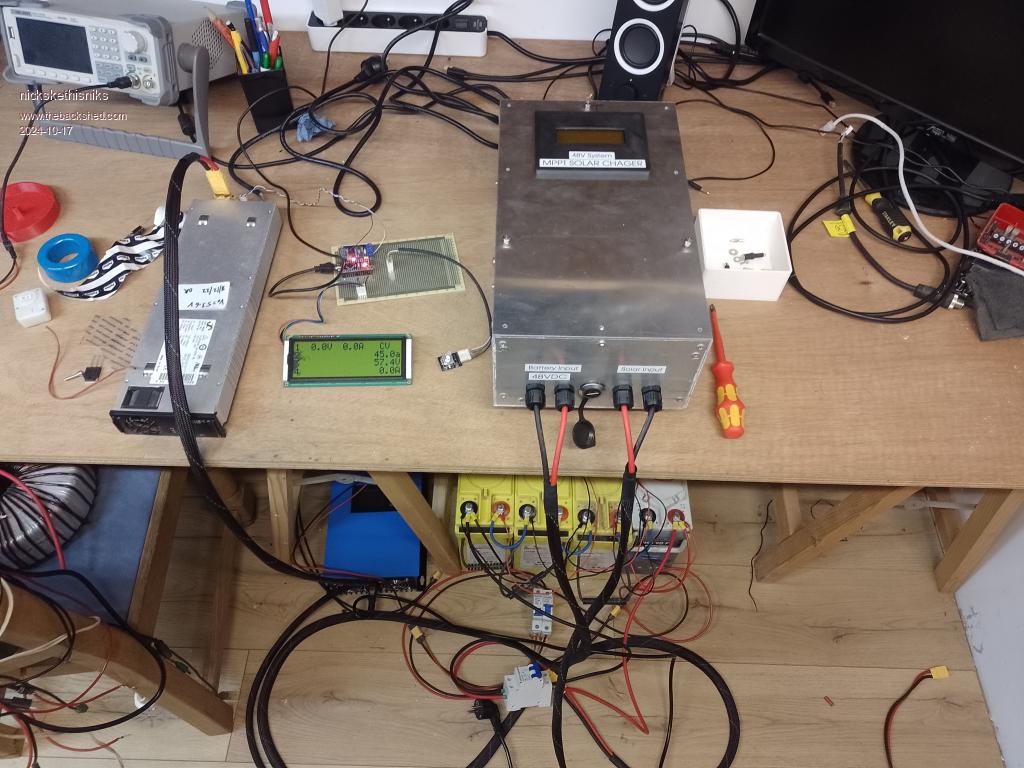
This is my test setup: Eltek power supply acting as a "solar panel" (actually CV/CC), a 90Ah battery as the load, but with a grid-tie inverter connected, which can act as an electric load (in theory, 2000W). So I can test non-stop on the bench, just compensating for the losses.
Lastly I need to make some scope measurements to be completely sure before hanging up the wall.
What I do noticed is the zero drift of the current sensors, I used acs758-50, (I admit they were the cheapest on ali I could find). It is bad, 2A I think at zero load after the 2h test. I will order some "LEM" brand ones to see if there is some difference. Maybe I should upload the newest firmware of poida's that is auto correcting. Not to important because this doesn't influence the mppt algorithm.
Oh what about some kind of DC EMI filter, I have a little bit of room left? Edited 2024-10-17 05:56 by nickskethisniks
Footnote added 2024-10-21 18:34 by nickskethisniks Wisemen, should have been "WISEGUY", sorry!
Revlac Guru Joined: 31/12/2016 Location: AustraliaPosts: 1278
Posted: 08:27am 17 Oct 2024
Copy link to clipboard
Print this post
Thats all looking very good, I like the build quality and the 3D printed LCD plate, "throttling-back function when running in high ambient temperatures" I think there is already in the settings, Cant see it at the moment, will check next time I have it in front of me. Cheers Aaron Off The Grid
Murphy's friend Guru Joined: 04/10/2019 Location: AustraliaPosts: 678
Posted: 08:49am 17 Oct 2024
Copy link to clipboard
Print this post
Nice build, well done .
You invited some comments regarding your case, the pop rivet method is OK for this size but I would steer clear of any riveting with an inverter enclosure. It is soooo much easier to access & adjust the components within the case if the sides & top are screwed on and can be removed individually.
For a small inverter (<1.5KW) I'd use 20x20x3mm alu angle for the frame without mitered corners as it then can be screwed together. If you need more experience with tapping threads, then this is a good excuse
For the cover panels I used 1.6mm aluminium sheet.
For a bigger inverter I make the frame from 20x20x2.5mm steel angle, welded together. The cover panels for this are also 1.6mm alu sheet.
Lastly, I do not see the wisdom of enclosing circuit breakers, why not have them poke through the front panel so they can be operated without tools?
Revlac Guru Joined: 31/12/2016 Location: AustraliaPosts: 1278
Posted: 08:48am 18 Oct 2024
Copy link to clipboard
Print this post
If the lid could be hinged then the circuit breakers would be quick and easy to access, no problem having them inside the box, I did my first charge controller that way and the modern plastic circuit breakers don't look aesthetically pleasing, mine didn't to me anyway.
Is there room to hinge the lid in it final location? Would probably be better as the screen and cables could stay in place, I nice polished aluminium handle might add to its good looks, though you probable come up with a better than I can anyway. Cheers Aaron Off The Grid
nickskethisniks Guru Joined: 17/10/2017 Location: BelgiumPosts: 477
Posted: 08:31am 21 Oct 2024
Copy link to clipboard
Print this post
Oh yes the throttling back function was indeed allready in the firmware but never saw it in action yet.
It feels very solid but it's not big compared to the dimensions I have in mind for the inverter. The rivets looked a very easy and simple solution for this one but they are not so strong.
Good tip to make the side panels accessible for servicing, I also would have liked to put the pcb on some aluminium 8mm thick plate to swap it out more quickly, allthough we build it to leave it like this for at least 10y or so, and not so big deal as having to replace an inverter board.
About the shifting zero currents, I noticed the 5V voltage regulator is not very stable under temperature variations, wich makes it worse. A 5V voltage reference capable of powering the sensors would help a lot.
Yes I know those breakers inside the case are not that smart if you want quick acces. But they make a perfect "terminal blocks", and are handy when experimenting. Putting them thrue the front panel would take me more time, but could a nice way, I could 3D print sort of a cap to hide them. The plan is to have external breakers to be able to disconnect any voltage going to the controller. Edited 2024-10-21 18:32 by nickskethisniks
-dex- Senior Member Joined: 11/01/2024 Location: PolandPosts: 104
Posted: 07:55pm 01 Nov 2024
Copy link to clipboard
Print this post
Radio silence lasted until you turned this device on! I know it's a metaphor, but as a user of these chargers and also a radio operator, I take this statement very literally. Yes, these MPPTs generate a lot of interference and something should be done about it, it's very good that you provided a place for EMI filters. I have several cores for this type of chokes, I will test them soon.
Great build, well DIY cases cost a lot, but the quality and durability effect make up for it. Beautifully made choke!
nickskethisniks Guru Joined: 17/10/2017 Location: BelgiumPosts: 477
Posted: 03:26pm 02 Nov 2024
Copy link to clipboard
Print this post
Yes, I never really took steps to measure or prevent interference. Honestly, I was just glad everything was working in the first place.
A few days ago, I took some initial oscilloscope measurements. I was a bit lazy and didn’t take the time to add ferrite beads to see if they would make a difference, but I did add a simple RC snubber.
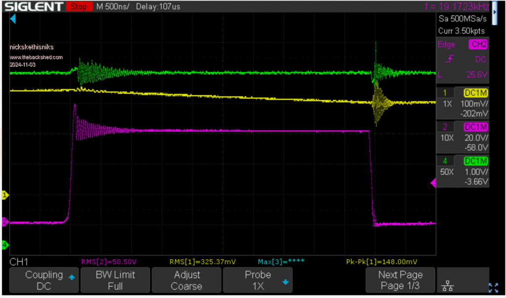
The first scope capture was taken for reference. The input was about 57.5V, the output was 51V, and the output current was around 30A. It would be great to connect two Eltek PSUs in series for a higher input voltage, but that’s still on the to-do list. You can clearly see the ringing at around 30 MHz.
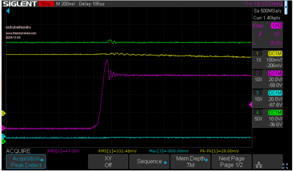
Next, I added one snubber with 2.2nF and 10Ω in series (did not calculate, just took something, it was barely warm so it could be improved) across the drain-source connection of a MOSFET. Here’s the result under the same conditions:
(excuse me for the bad scoop settings, yellow is current clamp 1A/100mV, green is input voltage, purple is DS )
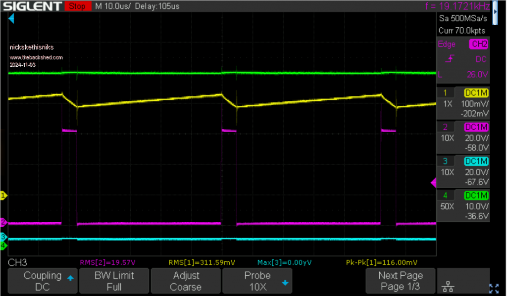
This is just to see some clear inductor ripple: Edited 2024-11-03 01:39 by nickskethisniks
nickskethisniks Guru Joined: 17/10/2017 Location: BelgiumPosts: 477
Posted: 09:02pm 02 Nov 2024
Copy link to clipboard
Print this post
How would you approach it and what kind of chokecore material would be suitable?
Was thinking about a low value 100n-10uf input capacitor and then an lc filter formed by an inductor and the onboard pcb capacitors. The inductor calculated based on the switching frequency devided by 10 for the cut off frequency? Edited 2024-11-03 07:06 by nickskethisniks


 "throttling-back function when running in high ambient temperatures" I think there is already in the settings, Cant see it at the moment, will check next time I have it in front of me.
 .
.