|

|
Forum Index : Electronics : Toroid Transformer calc
| Author | Message | ||||
| tonigau Newbie Joined: 15/10/2007 Location: AustraliaPosts: 4 |
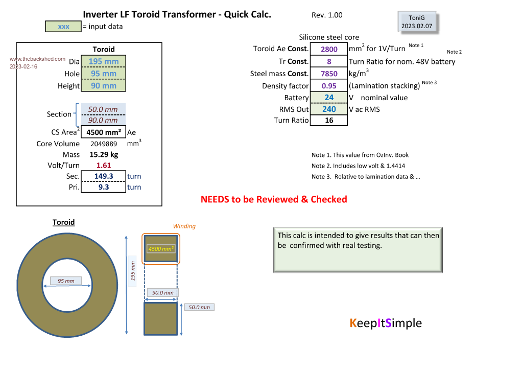
I made a quick transformer calc. in excel when I was evaluating different cores. It doesn't include wire fill, just gives Ae, V/T & winding turns. I would like if some experienced builders can check my calculation & constants as I don't have anything in the real world yet to verify against. Thanks Inverter ToroidTransformer Calc V1.0.zip  Edited 2023-02-16 19:46 by tonigau |
||||
| Murphy's friend Guru Joined: 04/10/2019 Location: AustraliaPosts: 648 |
Hmmm, we moved on since that 1V/turn you mention. To get a good low idle current it is important to calculate for a flux density of 10,000 Gauss or so. Easy with this online: calculator Note the units used!, especially the frequency. Just guess a number of turns for your core area and see what the Gauss reading results. Adjust the number of turns until the gauss reading is at or near 10,000. Use whatever number of turns that gives for a low idling current. |
||||
Revlac Guru Joined: 31/12/2016 Location: AustraliaPosts: 1024 |
I tried it a few times and could not get the numbers that I used when building my transformer, so it would be better if there was a place to enter the desired Tesla value. "Maximum Flux Density" Or this one https://www.electricaltechnology.org/2014/02/maximum-flux-density-bmax-calculator.html Not sure why that didn't work Murph Calculator Edited 2023-02-18 19:39 by Revlac Cheers Aaron Off The Grid |
||||
| Murphy's friend Guru Joined: 04/10/2019 Location: AustraliaPosts: 648 |
They both work the same for me Aaron. The trick is the 4 zeroes before the 5 in the frequency field. It really is not that difficult (for me  ) to guess a starting turns number. And one Tesla equals 10,000 Gauss. ) to guess a starting turns number. And one Tesla equals 10,000 Gauss.What the original poster presumed is 1V per turn which might not apply to every toroidal cross section if one wants a low idle current. One tesla is a much better staring point. It's no big deal if one turn equals 1.14V or any other not round number. Just divide the required voltage by that V/turn number and round up to the next full turn (not possible to have fractional turns  ). ).1 Tesla is a good compromise figure, one could try for a lower flux density but with the extra turns required the resulting reduction in idle current gets less and less. |
||||
| phil99 Guru Joined: 11/02/2018 Location: AustraliaPosts: 2135 |
" (not possible to have fractional turns )." With EI cores it's 1/2 turn increments as there are two holes. So for a toroid all you need is another hole! I f you really, really want that fraction drill a hole at the required fraction of the core width for the first turn to go through ;-) |
||||
| tonigau Newbie Joined: 15/10/2007 Location: AustraliaPosts: 4 |
Thanks for having a look. I made this calc. when I was looking at various existing cores to quickly compare & evaluate suitability to make a low power test inverter. (I like blowing up smaller stuff) I have updated to include Bmax. (Cell D18) & sheet 2. Yes, I have assumed some input to get results that seem reasonable(to me). There are gaps in my knowledge waiting for the right input. The online Bmax converters I looked at including daycounter specify Mhz , but seems the formula shown is actually hz input.?? ( I had to remove ^8) from the equation. Sheet 1 "TXF calc" The Volt/Turn of the calculation is based on the Ae Constant(cell J4) that I have fudged to "adjust" the secondary turns. I have done this just to get it working... Sheet 2 "Bmax from Turn" the sec. turns can be explicity entered with core data from sheet 1. I do expect the calc sheet to need some correction. I have since plundered a very cheap faulty 1400W UPS & the E-core seems quite good for resistance, 40mOhm & 400mOhm. Idle current might be a different story so might not be suitable for a 24/7 fridge inverter. (150W inverter fridge) Inverter ToroidTransformer Calc V1.2.zip Edited 2023-02-19 13:38 by tonigau |
||||
| Murphy's friend Guru Joined: 04/10/2019 Location: AustraliaPosts: 648 |
Maths has never been a strong point with me so I take your word for your calculations  . .The online calculators are really all one needs to get a transformer core re wound. I have a smallish E core transformer which I used for testing, works fine with a 150W floodlight load. I'm sure there is a calculator online that tells you what reasonable power a certain core can handle. |
||||