|

|
Forum Index : Electronics : Chinese Inverter HELP- purpose of LM324
| Author | Message | ||||
| azhaque Senior Member Joined: 21/02/2017 Location: PakistanPosts: 117 |
Hi all, I have this chinese inverter that I a trying to troubleshoot. .jpeg) It uses an EGS002 board to generate the 50 Hz sine wave. The main board has an LM324 ic on it. .jpeg) .jpeg) I want to know from people who may have worked with such a board, the purpose of the LM324. What I surmise is that the 324 can have something to do with the temperature, voltage and over-current feedbacks. Other than these there are no pins on the egs002 board that have any use for the 324. Am I on the right track or missing something? Help greatly appreciated. TIA azhaque |
||||
| Godoh Guru Joined: 26/09/2020 Location: AustraliaPosts: 458 |
I have a few of those inverters. From what I can gather the LM324 is part of the circuits that set Over voltage, over current, low voltage. Your board looks like you have modified it a bit, the addition of the potentiometer on the right side is one, on my boards that is the pot for adjusting output voltage. I have run one of my boards without the LM324 chip in and from memory it worked fine. I took the chip out to put a socket in to make changing it easier when I was trouble shooting the board, leaving the chip out did not seem to make much difference. Unfortunately there is very little documentation available for the boards, and they seem to change a lot. I have ordered a board from photos and a different configuration turns up, no documents, they just leave it to us to work out. good luck looks like your board has had a bit of moisture on it, I would clean it well first before doing much trouble shooting. Pete |
||||
| azhaque Senior Member Joined: 21/02/2017 Location: PakistanPosts: 117 |
Thanks for the reply Pete. The board had been running for about 3 years powering a part of the house. Earlier 2 mosfets failed and I repaired it and it worked fine. Your observation is keen. Earlier on while replacing the mofets I modified the voltage feedback circuit. It was a poor design and had 230 VAC coming into the board for sampling the output voltage. That was dangerous to work with. So I added a 12 volt transfo outside and connected 12 Volts AC while modifying the sampling variable resistor. That has worked OK for me. Subsequent designs by the chinese manufacture follow the same topology by adding a small transfo on the board, thus avoiding sampling the mains voltage directly. However the mains voltage is still connected to the board albeit in a fairly isolated manner which is much better. As you mentioned, the 324 is for setting various values of voltage and current to feed back to the main ASIC Chip- the 8010. However the 4 pots around 324 have mandarin phonetics written in English which is Greek for me  . So I wondered if someone can help me decode the mandarin. It will save time in tracing out the whole board. . So I wondered if someone can help me decode the mandarin. It will save time in tracing out the whole board. Pakistan is in economic trouble with a seriously depleted foreign exchange reserve. As such imports are becoming an issue. So I need to fix the board myself. I was hoping someone having experience with such a board could guide me. Anyway thanks again for the reply. Hopefully someone who is knowledgeable about it would see this thread and help out. Edited 2023-02-15 19:04 by azhaque |
||||
| tinyt Guru Joined: 12/11/2017 Location: United StatesPosts: 438 |
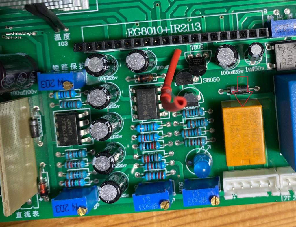
I have a similar board but not exactly the same. I am guessing that the pot near the corner and the pot near the white connector is for overvoltage and undervoltage but I don't know which is which. The 2 sections of the LM324 connected to these two pots control the orange relay thru the two transistors. if the two pots are adjusted for the desired operating voltage coming from the battery, the relay will be energized. When the relay is energized, contacts of the relay apply the 12 volts and 5 volts (thru a regulator) of the EGS002 . The other two un-modified pots control the other two sections of the LM324. The output of one feeds the IFB pin of the EGS002 and the other feeds the resistor jumper going to the EGS002, I don't know what it is for. Edited 2023-02-16 00:01 by tinyt |
||||
| azhaque Senior Member Joined: 21/02/2017 Location: PakistanPosts: 117 |
Thanks for the reply Tiny. My board doesn't have a relay. But I guess many variants exist. As I mentioned in my opening post, each pot has an expression in mandarin probably indicating the function of the that pot. I put each of the 4 expressions to Google Translate. I was pleasantly surprised by the results that I have copied below.     Not bad, huh. The best one is 'have eaten' which I think is for'battery overvoltage'.  . .As you mentioned, these pots control the under/over voltage and current. The 324 is probably wired as a window comparator for current feedback to the IFB pin of the EGS002 board (Pin #1). When the board is switched on, the red LED blinks indicating current overload resulting in shut down. This is the problem I am facing, for which any help is greatly appreciated. TIA. Edited 2023-02-16 01:52 by azhaque |
||||
| tinyt Guru Joined: 12/11/2017 Location: United StatesPosts: 438 |
One my board the yellow/orange part is a relay.  It looks very similar to what is on yours. Also, mine has two dual opamps while yours has one quad opamp. Edited 2023-02-16 01:43 by tinyt |
||||
| poida Guru Joined: 02/02/2017 Location: AustraliaPosts: 1418 |
Hi Azhaque I have used and abused this particular board a lot in the past. there are 5 trimpots on the board. Obviously one is for output voltage setting. The other 4 are located close to the quad opamp. trimpot #1 is used to set low voltage shutdown. I think of it as a simple comparitor, with the output going to the transistor base, which will then control the relay to connect 5V supply to the EGS002 module #2 is used to set DC supply over voltage shutdown. Again it's a comparitor and it's output can also disable the 5V output from the relay. #3 is "overload", a slow acting current limit, this time it's a high gain amplifier (I think) and it's connected to the IFB pin, (pin 1) on the EGS002 It takes the small voltage present across the wire shunts on the 0 V DC supply. #4 is a fast acting over current thing, and the output of the opamp is connected direct to the pin1 of the LM393 dual opamp, bypassing the low pass filtering that is present on the EGS002 module. This signal goes direct with no filtering to the shutdown pins of the IR2110 gate drive ICs. This signal can disable PWM very quickly, within a few uSec and it is driven directly from the output of the LM324. There is a series resistor inside the shrink tube, this limits current so the LM393 output will not see too high a load. Testing the board on the bench showed the fast acting over current circuit to behave very badly. I saw very large and fast high current transients powered into the toroid or output transformer. The toroid nearly jumped up off the workbench sometimes. I saw no need for this and disabled this circuit for all future testing and eventual year long use running my home. In the case of #3 the slow acting overload circuit, the baviour is very different. this time the opamp's output is directed to the EGS002 pin 1 IFB pin which is then going to another opamp, on board the EGS002, to eventually go to the EG8010 IFB pin 14. When pin 14 goes above 0.5V for about 0.6 second, the PWM will shut down immediately and then attempt a soft startup, first powering up fo 0.1 second to see if the overcurrent or short circuit still exists. IF no over current (i.e. > 0.6V is present) then the soft start will progress and the inverter will run. There are two over current protections. One based on pin 14 of the EG8010 and one based on driving the shutdown pins of the IR2110 gate drive ICs. wronger than a phone book full of wrong phone numbers |
||||
| azhaque Senior Member Joined: 21/02/2017 Location: PakistanPosts: 117 |
Many thanks for this very elaborate reply, Poida. Helps a lot in visualizing the circuit and improving my understanding of it. Saves me the pain of tracing out the board. Very grateful. As mentioned above, I know that one since I fiddled with it earlier. It feeds directly into the VFB pin, controlling the set-point for the o/p voltage (230 VAC). Oops. Pete had mentioned a relay in his post. I didn't remember having one on my board so I figured it must be a different variant. Now when you said it I went to do a double check and found that the relay is there. Sorry Pete. I guess my 64 years are getting my neurons.  This raises a question. I had assumed that the VFB pin on the 002 board is being used for over and under voltage shutdowns. But then this wasn't squaring with the under/over voltage pots that you have mentioned above. Is it to say that the over/under voltage are associated WITH THE BATTERY (48 vdc) and over or under BATTERY voltage fires the relay which cutsoff the +5 volts supply. The VFB pin is for the mains voltage control and has nothing to do with battery voltage related events. Secondly the battery over volts protection was working OK. The battery is charged by the o/p of PWM charge controllers. In the morning at around 8:00AM when the sun is really shining and the charge controller o/p is in bulk charging mode, the battery voltage would rise above the over voltage set point, causing the inverter to shut down. Disconnecting the input wire from the solar panels would cause it to restart. By the way maybe this has somehow stressed out the LM324 op/amp performing this duty. Am I on the right track here? I understood that. Low side current measurement implemented here. I think the op/amp performing this duty on my board is the culprit. I measure 0 volts to the IFB pin, which should be around 0.5 volts as per datasheet. Hahaha, the pitfalls of low side current measurement, all the crap creeping into the measurement arrangement. I also wondered what this flying lead was for. I thought it was an error that was discovered after the main board PCB was manufactured. I guess it was needed because the 002 board is the GIVEN in this design. Reviewing similar inverters show that later versions still have the flying lead. Thanks for this elaborate run down on the board Poida. Let me sleep over it and then apply this new found insight into troubleshooting the board. Regards and Good wishes from Pakistan. |
||||
| tinyt Guru Joined: 12/11/2017 Location: United StatesPosts: 438 |
Hi azhaque, This is my circuit tracing of the 48V 10000 watts inverter. CHIN INVERTER(MOD2).pdf Even though it is not the same as yours, it might help in your troubleshooting. |
||||
| azhaque Senior Member Joined: 21/02/2017 Location: PakistanPosts: 117 |
Thanks a million Tinyt. It will certainly help. God bless you Azhaque |
||||
| poida Guru Joined: 02/02/2017 Location: AustraliaPosts: 1418 |
thanks tinyt this will help get him going again. wronger than a phone book full of wrong phone numbers |
||||
| azhaque Senior Member Joined: 21/02/2017 Location: PakistanPosts: 117 |
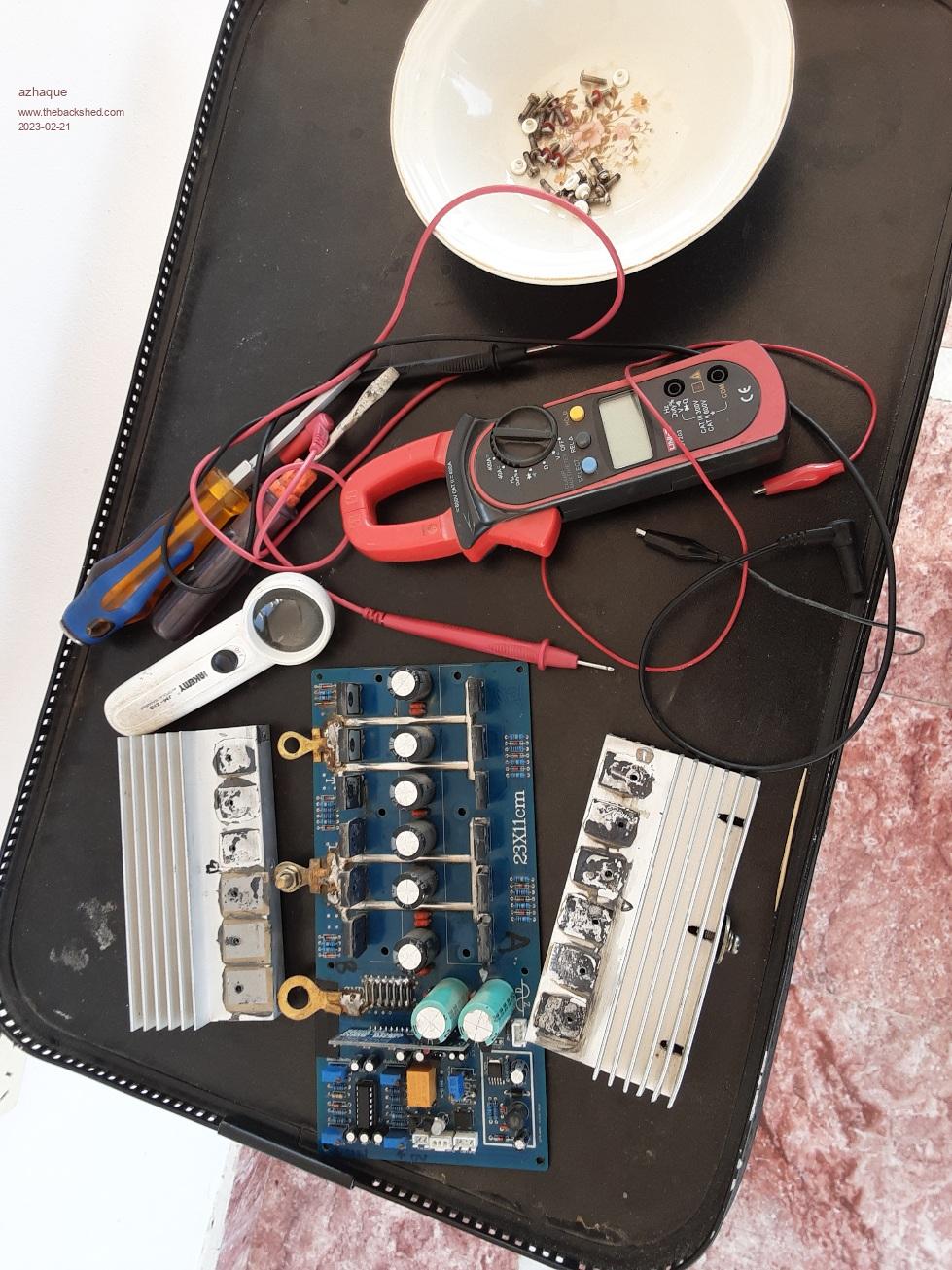
Hello everyone, Thanks to Tiny I got the LM324 figured out. The circuit is almost the same except the High Battery Voltage to 12 vdc converter. The LM324 has been replaced by LM358s. However the bad news is that after connecting it all back and throwing the breaker things went POP and the breaker tripped. On checking found 6 out of 12 mosfets blown  . Couldn't figure out the reason why it happened. Maybe just because the inverter was running 24/7 for 3+ years, the mosfets just got tired and gave up their ghosts. Luckily I have 4008s in spare, so I am not stranded completely. Have dismantled it again and ready to replace the busted fets. . Couldn't figure out the reason why it happened. Maybe just because the inverter was running 24/7 for 3+ years, the mosfets just got tired and gave up their ghosts. Luckily I have 4008s in spare, so I am not stranded completely. Have dismantled it again and ready to replace the busted fets. Edited 2023-02-21 14:58 by azhaque |
||||
| azhaque Senior Member Joined: 21/02/2017 Location: PakistanPosts: 117 |
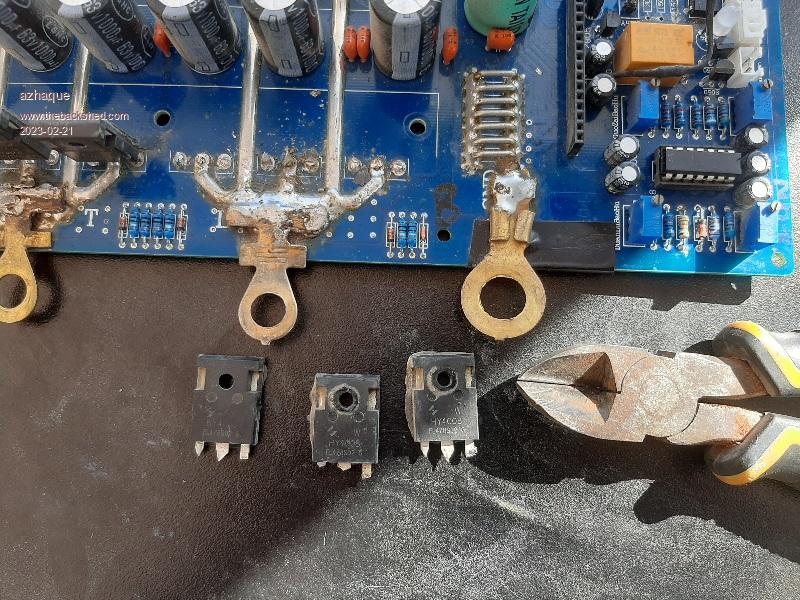
 Cut out 3 fets showing shorts between Gates and Drains. All dead as a doornail. Will clean up and insert new 4008s with crossed figures.  Edited 2023-02-21 15:28 by azhaque |
||||
| tinyt Guru Joined: 12/11/2017 Location: United StatesPosts: 438 |
If it were me, I would also replace the EGS002 as the mosfets could also have busted its driver chips. Or, install only one mosfet at each leg of the H bridge, apply power without load and hope that nothing blows again. Also, looks like the mosfets with the ring lugs have to be insulated from their heatsink. Edited 2023-02-22 00:08 by tinyt |
||||
| azhaque Senior Member Joined: 21/02/2017 Location: PakistanPosts: 117 |
Good advice Tiny. The Gates and Drains of the blown mosfets show 000 resistance which means that 50vdc did get to the o/p circuits of the 2110 driver chips; however briefly. So I will replace the 2110s before putting it in lest it blows up the replaced mosfets. Thanks and regards Azhaque |
||||