rustyrotors
Newbie

Joined: 07/01/2023
Location: United StatesPosts: 36 |
| Posted: 03:11am 06 Feb 2023 |
 Copy link to clipboard Copy link to clipboard |
 Print this post |
|
my diy solar journey starts about 10 yrs ago, when i spent a lot of money on an aims 6kW aio unit and quickly discovered it draws 180w at idle.. i dont know how they expect people to use the dang thing offgrid?? its built in solar charger could only handle 60A, it would take pretty much all of that just to keep up with idle draw. so i got discouraged, and i did not really mess with it until about a year ago. thats when i stumbled across this forum, discovered you guys were diy'ing your own inverters for cheap. so i decided to give offgrid solar another try, and have been reading up on all the great info posted here
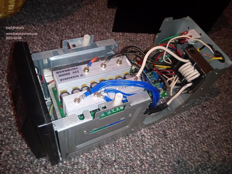
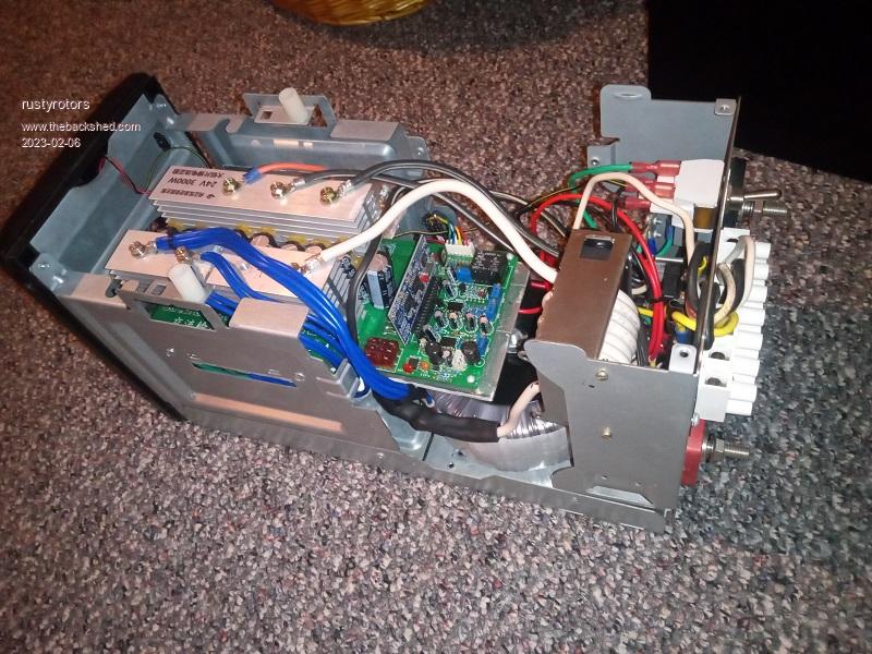
its hard to find large toroid trans in the US, but i did found these, only 500VA but cheap. i run two in parallel, handles 1500W with cooling, my loads dont go over that
https://www.antekinc.com/an-5415-500va-15v-transformer/
i used an aliexpress sunyima 3kw egs002 inverter board, which quickly blew up all its caps and most of the fets on its first test load. thats when i discovered posts on here about the egs002 over current protection bugs. I removed U4, shorted C19 and C24 to completely disable overcurrent protection. also increased the deadtime to 500ns, the idle current seemed to be a bit lower than the default of 300ns. I replaced the 1000uF caps with biggest i could fit on the board 4700uF. the only current protection now is 15A breakers on each 115v output legs
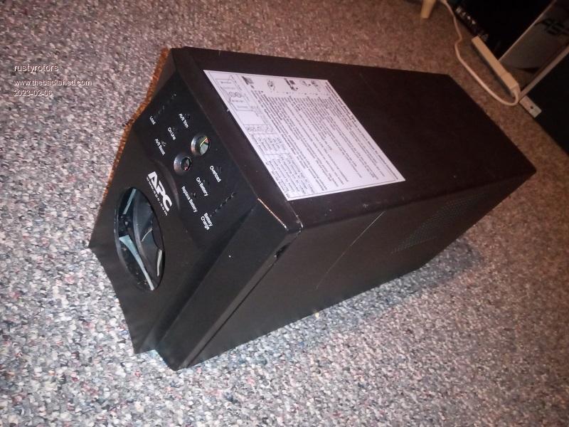
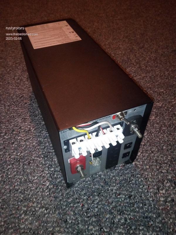
the choke is a E65/32/27-3C94 core with 1mm gap and 6.5 turns. more turns would drop idle current another watt or so, but also seemed to add wiggles to the sine output, so left it at 6.5T. i measured a little over 100A sat current and about 30uH. it resonates around 90hz with a 2.2uF output cap, idles at 14W with the fan running. i used an old APC ups case. it has been running my house for about 6months now no issues, very reliable, and cheap! all in only cost me about $350 in parts
i read a few others had issues with a wiggly sine output. I noticed a potential cause is a buzzing choke, i got rid of the buzz by adding tape as pad around the choke where it sits in its clamp, and wiggles went away
i have a question about fet gate resistance.. i noticed on the sunyima board, they have a single 4R7 resistor in parallel with a reverse diode, a 10k pull down, then branches to 6 mosfets. I understand the 4R7 resistor limits current from the gate driver and slows turn-on time, and the diode speeds up turn-off time, helping prevent ringing and shoot through. But does the diode not overload the IR2110 gate driver when gate switches off, since current not going through a resistor? or does the IR2110 internally limit current? what about using something like a TLP350 driver, which is rated for 2.5A max, would a reverse parallel diode overload it? my old aims board uses TLP350 and has 47R on each fet gate, but with no reverse diodes


 |
wiseguy

Guru

Joined: 21/06/2018
Location: AustraliaPosts: 1156 |
| Posted: 06:01am 06 Feb 2023 |
 Copy link to clipboard Copy link to clipboard |
 Print this post |
|
I like use of the APC UPS, re-housing the inverter, it turned out quite neat and compact.
The 4R7s do not only limit current but are also related to controlling/limiting turn on time of the FET's and their use may also aid with package dissipation.
The data sheet of the IR2110 does not give an absolute maximum of output current for its output drivers.
It only states in the static section that minimum current is 2A and typically it is 2.5A, it would therefore be reasonable to assume that the output stages are current limited/protected.
I have seen the use of the diode with no resistor in many applications, but it was a good question !
If at first you dont succeed, I suggest you avoid sky diving....
Cheers Mike |
Solar Mike
Guru

Joined: 08/02/2015
Location: New ZealandPosts: 1138 |
| Posted: 08:46am 06 Feb 2023 |
 Copy link to clipboard Copy link to clipboard |
 Print this post |
|
Newer Mosfet drivers normally specify their internal source and sink impedances, along with max pulse current out (source) and in (sink), knowing those specs and the gate resistance of your mosfet, the best value gate drive resistance can be calculated.
The IR2110 spec doesn't have this information, however it does have a graph showing max sink current against voltage, at 12 volts the device can sink just under 2 amps, this increases with voltage. So if your gate resistances all have reverse diodes across them and the mosfet gate bias voltage is near 12V then the max current will be limited to approx 2 amps; so no you won't blow it up.
A good reason why the reverse diode is used, is to lower the source gate drive impedance as seen by the mosfet; at 0v drive ie mosfet turned off, the device is less susceptible to being turned back on due to fast rising voltages on its drain getting into the gate circuit due to the mosfets internal drain gate capacitance (miller effect). A very low gate drive impedance will limit any voltage rise at the gate as would perhaps be the case if the gate drive resistor was in play.
The TLP350 is a very old device, seems to have similar output specs to the IR2110, probably be ok if bypass diodes used, however I would not recommend the device for any new inverter design, its quite slow and more suited as a IGBT driver.
Mike
Edited 2023-02-07 09:55 by Solar Mike |

