| Author |
Message |
Solar Mike
Guru

Joined: 08/02/2015
Location: New ZealandPosts: 1138 |
| Posted: 05:00am 17 Jan 2023 |
 Copy link to clipboard Copy link to clipboard |
 Print this post |
|
Building several high power inverters at the moment along with the Battery management systems, one thing they all have in common is a requirement to turn off the DC battery input to each inverter should the battery get depleted, and to have a pre-charge facility for the main storage capacitors at first turn on.
In the past I have used those high current vacuum relays + an additional pre-charge relay and some timers, switched by either the BMS or the inverter, this functionality seems an ideal candidate for a stand alone modular component using a bunch of suitably rated mosfets and a small cpu controller.
A couple of the batteries are 100 volts Lifepo4, the other 48 volt lead carbon, average load currents will be between 100 and 200 amps. I want something easy to put together and simple to setup and fit on to a 100 x 100mm PCB. Costs should work out better than relays, but will take up more room.
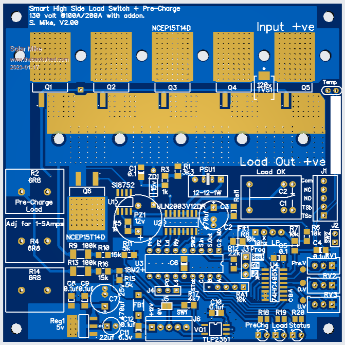
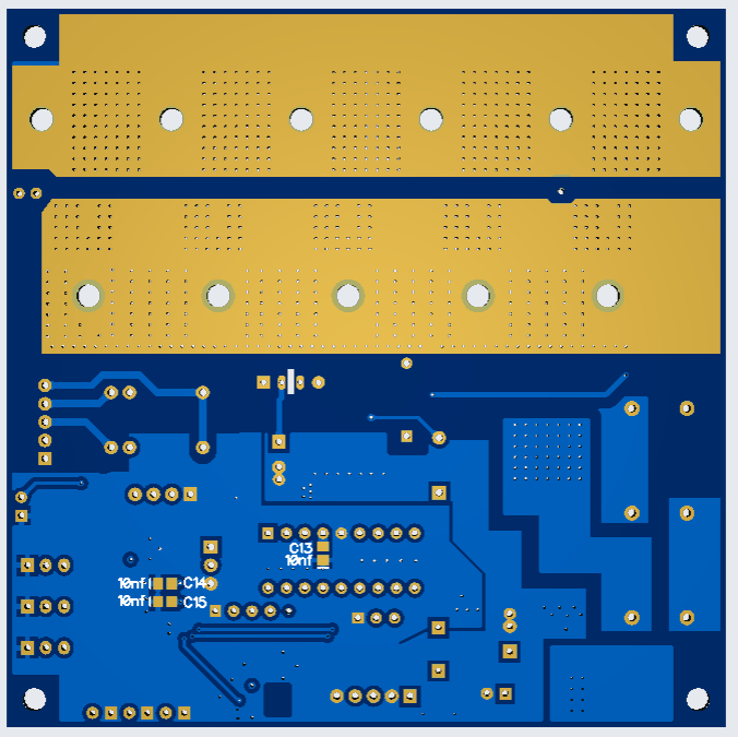
Here is my prototype design for a high power high side switch, its built on a 4 layer PCB and uses a PicAxe 18M2+ CPU to measure the battery and load voltage (inverter caps); three pots set the pre-charge voltage, battery under\\over voltages. I have used cheap readily available mosfets NCEP15T14D, 150v 140A, 6.2mR, one for pre-charge and 5 or 10 in parallel for the main switch load.
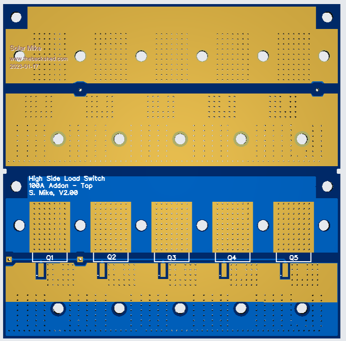
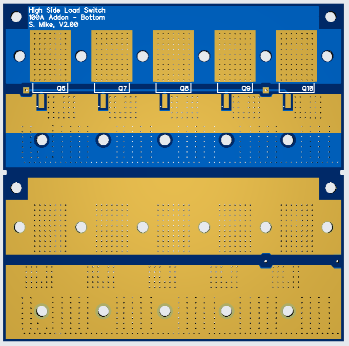
Two 15 x 3mm copper bars bolt under the mosfets along with an alloy 32 x 25 x 3mm angle (if required) for heat dissipation. The main PCB has 5 load mosfets, another 5 can be bolted on the back (Addon small PCB) sandwiching the copper bar between them. The addon PCB has 2 boards on it, they can also be bolted back to back for additional current or used for other purposes.
Main PCB 100 x 100:
Expansion Addon:
Will draw up the schematic next...
Cheers
Mike |
| |
KeepIS

Guru

Joined: 13/10/2014
Location: AustraliaPosts: 1679 |
| Posted: 05:29am 17 Jan 2023 |
 Copy link to clipboard Copy link to clipboard |
 Print this post |
|
Brilliant, just what I was thinking about, only better.
It's all too hard.
Mike. |
| |
Solar Mike
Guru

Joined: 08/02/2015
Location: New ZealandPosts: 1138 |
| Posted: 11:28am 18 Jan 2023 |
 Copy link to clipboard Copy link to clipboard |
 Print this post |
|
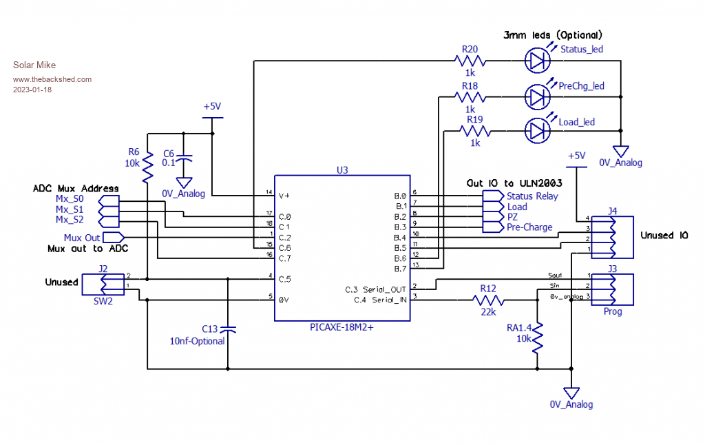
Schematic done, no errors on the pcb, made a couple of minor resistor changes and brought out unused CPU pins to pin strips.
Wont post the pcb again until I get a working example.
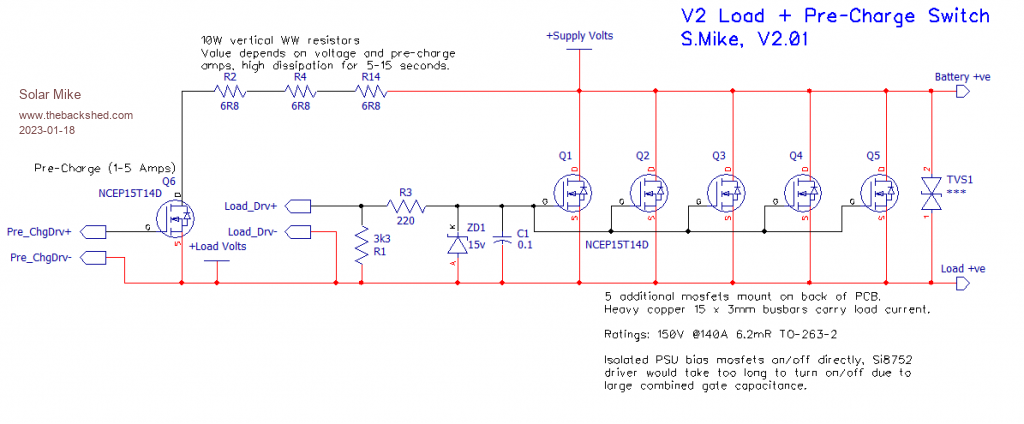
Schematics:
Main Load Switching, having 5 to 10 or more parallel mosfets presents too high gate drive capacitance for using one of those voltage generating isolator driver chips, would be way too slow; so I just use a 1W 12-12v isolated PSU, note they specify a minimum load resistance for correct operation.
The single pre-charge mosfet uses the Si8752.
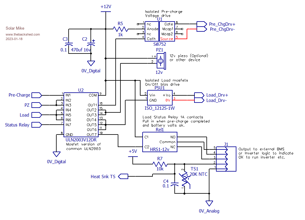
CPU output buffer ULN2003V12DR is used for the switching, this buffer uses mosfets internally and can accept 3.3-5v logic input, the device has pull down resistors and protection output diodes so makes a good compact solution for boosting IO.
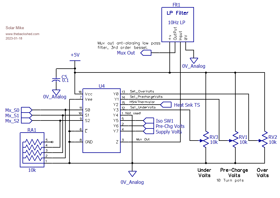
CPU ADC inputs, rather than using a bigger cpu chip, I have used an 8 input mux, the selected input goes via a dual Op Amp low pass Bessel filter module to the CPU ADC, there is a lot of noise and EMI on the battery and inverter power lines, the filter gets rid of it all and its very low output impedance is ideal driving the CPU ADC input.
This is also one of the reasons for going to a 4-layer PCB, the two internal ground plane layers help with EMI and enable optimum layout, especially earthing, ie Star Earthing system used.
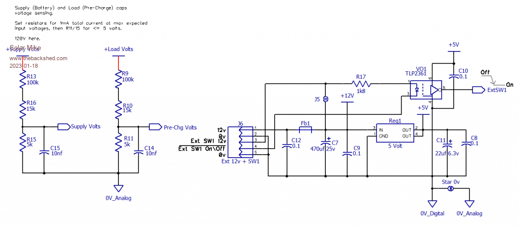
Voltage sense and Power, the PCB runs off 12v supply passed in on J6, a small 1A linear reg used for 5v.
Opto logic switch VO1, is used to turn the load on\off as required.
CPU, Picaxe-18M2+ used here mainly because I have a number lying around and a Pi PICO module is just too big. Speed isn't really an issue; however I'm very tempted to try out one of the PIC Basic Compilers on one of these chips to see what performance improvements are to be had.
Several unused IO pins have been brought out to pin strips.
Cheers
Mike |
| |
Solar Mike
Guru

Joined: 08/02/2015
Location: New ZealandPosts: 1138 |
| Posted: 03:22am 19 Jan 2023 |
 Copy link to clipboard Copy link to clipboard |
 Print this post |
|
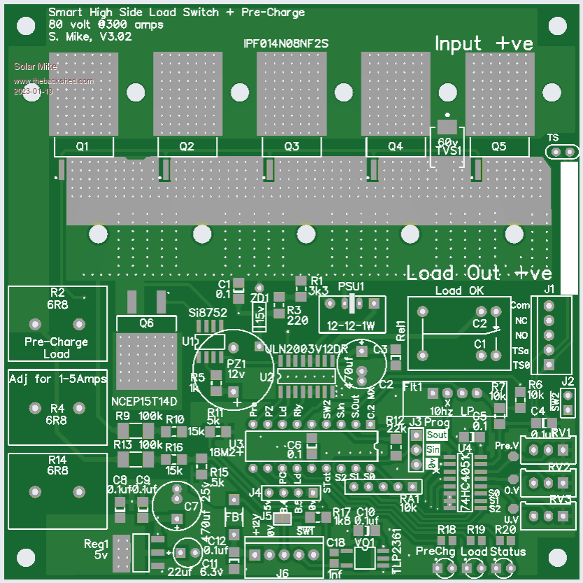
I have a look at some of the lower voltage mosfets in the TO-263-7 package, these newer models are arranged differently internally, with no connection wires, direct bonding is used making them very robust and low on resistance.
For 50 volt systems it makes better sense to use a lower voltage mosfet with only slightly higher cost, Element14 have good stocks of the IPF01408NF2S, this 80 volt rated at 282 amps and 1.2mR device is < $6 each and only 5 devices are required for 300 amps; the addon mosfet PCB isn't required, which makes it easier to build, probably no extra heatsinking will be required, even better. At 200A power lost is only 12 watts.
Have changed the PCB to accommodate 5 of the newer mosfets to suit 50v setups, the other board remains the same for 100v, won't use the addon PCB as the higher amperages are not required.
V3 PCB 100x100mm:
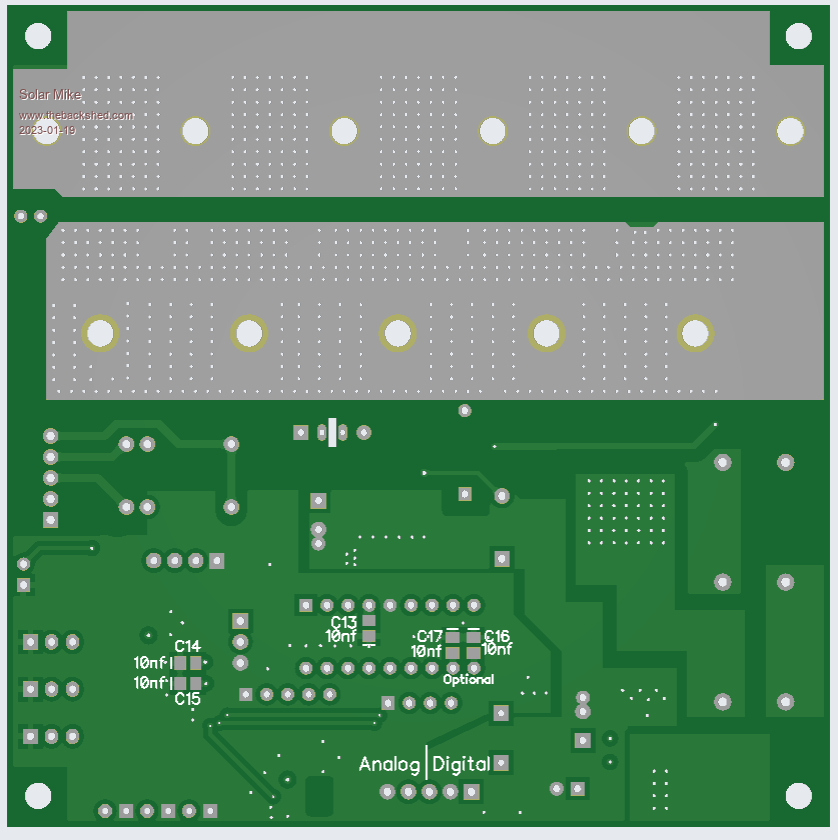
4 layer PCB's are US$7 for 5 at JLCPCB
Cheers
Mike |
| |

