
|

|
Forum Index : Electronics : Why do we test the inverter without the large DC caps installed
| Author | Message | ||||
| poida Guru Joined: 02/02/2017 Location: AustraliaPosts: 1418 |
I always test a new inverter power board first without the DC bulk caps installed. This way I can limit the current the FETs will be exposed to. IF the caps are installed then they will charge up and deliver their charge into the FETs and that will be not under my control. How much current could a capacitor deliver should the inverter board switch both HIGH side and LOW side at the same time due to improper drive signals or not quite right gate drive? I was always wondering that. The test cap is a Aliexpress 100V 10,000uF cheapie, costs about $6 each or a bit more now. These caps are not robust, I blew one up when I fed it 95V for a day. Maybe they are relabeled 60V caps or something. So I soldered a 1mm diameter copper wire, 5 inch long onto a cap terminal. I measure the resistance and get 19mV drop at 5 Amps This will be the current sense. 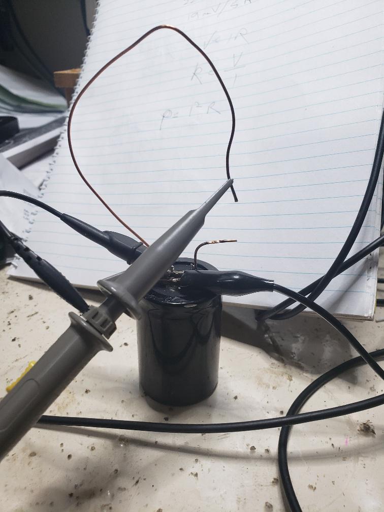 I charge the cap to 50V and then short it, capturing the voltage across the copper wire. the event: 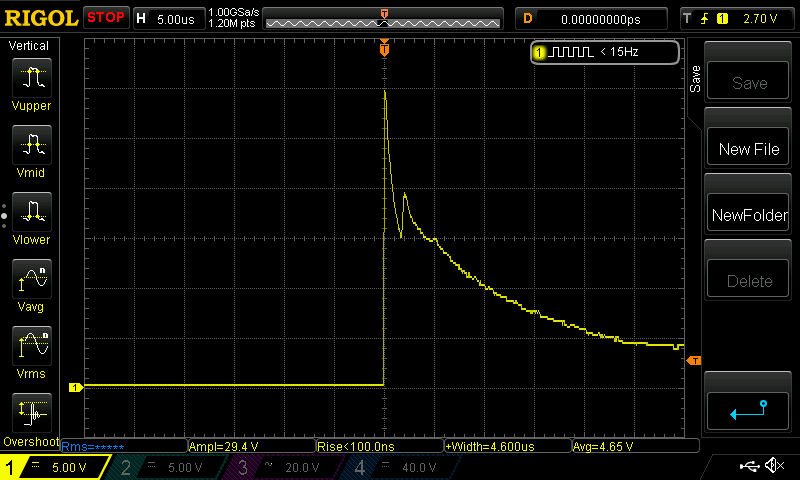 The peak is 30V I did not believe that so I did it again, checking the voltage divider and DSO settings. Must have made a mistake.. no mistake. 30V / 0.019 * 5 Amps = 47,000 Amps I must smoking some really good gear tonight. 47,000 Amps? I would like it if other people here would do the same test, to confirm or not what I have seen. maybe there is some other effect here adding to the voltage ac\\\\\\\\Anyway, the inverter power board has 6 of these caps installed in parallel and so it would appear there is a very huge amount of current available on the DC supply. Should the FETs be switched on both high and low sides then this current will be dumped through them. No FETs can handle this sort of current. On occasions I have tested a board with caps installed and the FETs blow. It comes with a quiet "tick" sound. But with no caps installed and a current limited power supply you can get away with murder. wronger than a phone book full of wrong phone numbers |
||||
| Solar Mike Guru Joined: 08/02/2015 Location: New ZealandPosts: 1138 |
Extraordinary, we are all playing with fire... In my first year of electrical engineering at university many many years ago, the tutors wheeled out on a trolley a large 1 farad cap, charged it to 50v, then slung a 6 meter length of 2.5mm copper wire up to the roof so the ends dangled down. Hooked up to the cap via a large solenoid. Everyone in the lecture has was handed a small compass and was told discharging the cap into the wire will cause a large magnetic field which we will all observe as a movement in the compass needles. What do you think happened as the solenoid was closed and the cap discharged into the 1 loop coil. A: the compasses spun. B: The copper coil wires moved None of the above, there was an almighty deafening explosion and green flash, the air was full of vaporized copper and smoke, there was no time to even think about watching to see if the compass moved. Not a trace of the copper wire remained, the experiment was never repeated. Cheers Mike |
||||
| poida Guru Joined: 02/02/2017 Location: AustraliaPosts: 1418 |
I was on drugs 30V / 0.019 = 1579 and then times 5 gives me 7,895 Amps Now that is reasonable. Only 7,900 Amps peak instead of 47,000 Where did I get that 47K from.. Solar Mike, how about you do this test? Only take about 10 minutes. I'd love to see if this can be repeated. This test is realistic. HY4008 resistance when fully on is 2.9 milliOhms the wire I used as the current sense is 0.019V when 5 Amps is passed through it. R = V/I so resistance of the wire = 3.8 milliOhms Edited 2022-12-02 22:14 by poida wronger than a phone book full of wrong phone numbers |
||||
| mab1 Senior Member Joined: 10/02/2015 Location: United KingdomPosts: 209 |
Does the copper get warm? Copper isn't used for current shunts as it does have quite a significant temp coef - might be exaggerating your results? |
||||
TassyJim Guru Joined: 07/08/2011 Location: AustraliaPosts: 6098 |
You have the inductance of the loop made with your copper wire. You probably also have to consider "skin effect". That is something we worry about with AC, especially high frequencies. Both of these may increase the impedance of the circuit but I can't guess by how much. You might have ended up with a resonance (L and C in series) to make life even more interesting. Jim Edited 2022-12-03 06:20 by TassyJim VK7JH MMedit MMBasic Help |
||||
| phil99 Guru Joined: 11/02/2018 Location: AustraliaPosts: 2135 |
Yes, large current transients can be quite complicated. Long, long ago while studying HV Transmission and System Protection we were told to ensure the voltage rating of everything was overrated by 3 times. A short circuit would create voltage transients of up to double the normal peak voltage elsewhere on the transmission line. The ends of the line were especially vulnerable. If I recall correctly fully describing a short circuit event took a couple of pages of calculations. . Edited 2022-12-03 10:11 by phil99 |
||||
| Murphy's friend Guru Joined: 04/10/2019 Location: AustraliaPosts: 648 |
Those 3.8milli Ohms were at 5A, the wire was cold then. That resistance instantly got much much higher with the short circuit current. I very much doubt that your quoted peak short circuit actually flowed through that wire. Had it, that 1mm wire would vaporize instantly, you did not mention yours did so. You might repeat this experiment with a disposable mosfet doing the switching, eliminating possible doubtful contact of touching wires. Perhaps you could take bets which blows first, the wire or the (100A rated?) mosfet  |
||||
| poida Guru Joined: 02/02/2017 Location: AustraliaPosts: 1418 |
I agree that the skin effect likely makes for the huge voltage across the wire. The very fast change in voltage over time means a lot of high frequency power, and high freq flows mainly on the outside of the wire more and more as the freq rises. I measured the wire using DC so it used the full area of the wire in the resistance. Litz wire will give different results. Today I had another go. This time, a poor old HY4008, with the Gate driven by 12V, switched on via a push button. A 1K resistor is used to pull it down to ground to ensure it's only on when I press the button. 50V on the cap and I press the button.. volts across the Source and Drain: 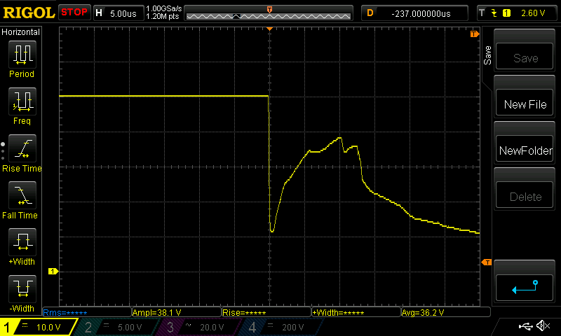 And there were no flames. I am disappointed But the FET did get destroyed and finished up a dead short Is it worth it doing it again at 1/2 energy and 1/4 to see what it can survive? energy in the cap is Volts squared times capacitance I did a test with 12V and the FET could handle that. this is 12 x 12 x 10,000 / 1e6 = 0.7 Joules 50V was destructive and that is 12.5 Joules wronger than a phone book full of wrong phone numbers |
||||
| Murphy's friend Guru Joined: 04/10/2019 Location: AustraliaPosts: 648 |
That graph has me curious, why the voltage re bounce? I would have thought a short MosFet has zero volts across source/ drain. |
||||
| poida Guru Joined: 02/02/2017 Location: AustraliaPosts: 1418 |
I think it can deal with the current for a little while, then it goes a bit linear and then some cells overheat/blow up/go short and then it completes the destruction. I tried it at 25V, which is 1/4 energy and it survived two conduction events 1/2 the energy is 35.4 V and now I try that.. a different timebase this time. 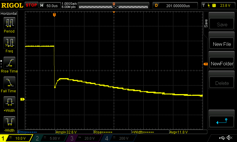 the HY4008 survived 3 dumps of 35.4V of the 10,000uF cap the current should follow an exponential decay curve and it seems to after the first part of the switch ON period. I now give it 50V and it can not deal with it and goes short circuit. again the bounce 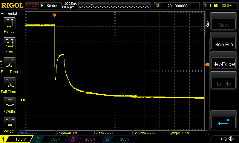 wronger than a phone book full of wrong phone numbers |
||||
| wiseguy Guru Joined: 21/06/2018 Location: AustraliaPosts: 1156 |
Peter, thanks for the pictures and generous donation of a few sacrificial FETs all very interesting. I agree that your experiment at 50V did yield a true peak current around ~5,000A+ albeit very briefly. Any chance whilst you have the same setup & capacitor etc that you have another FET you are prepared to risk in an experiment at 34V again but this time with Gate voltage around 20V - 22V ? �I am wondering if that instantaneous voltage dip before peaking again might be much reduced with more gate volts ? I have a theory that the gate impedance of ~ 3 Ohms, actually starts at zero, closest to the cells at the Gate terminal and increases to ~3 Ohms at the furthest point away. Thus when the voltage on the drain collapses so fast, the miller effect actually shuts down a heap of cells at the far end of the gate structure as they are less "stiff" therefore increasing the VDS momentarily. If the gate is driven higher/harder initially then maybe the effect will be reduced as they have a higher potential to fight before they get to the gate's off threshold voltage ? A 1u+ film or ceramic capacitor close to the +supply side of the switch and the other side of the cap close to the FETs source will help drive the gate best. Keep up the good work ! Edited 2022-12-06 00:35 by wiseguy If at first you dont succeed, I suggest you avoid sky diving.... Cheers Mike |
||||
| poida Guru Joined: 02/02/2017 Location: AustraliaPosts: 1418 |
just got home and had a beer. This FET is different. I am using those which seem to "test OK" after an inverter blowup. So there is none of this pronounced hump. 35.4V, 12V gate voltage and no cap to boost the Gate drive This the the test conditions of the above examples as well. 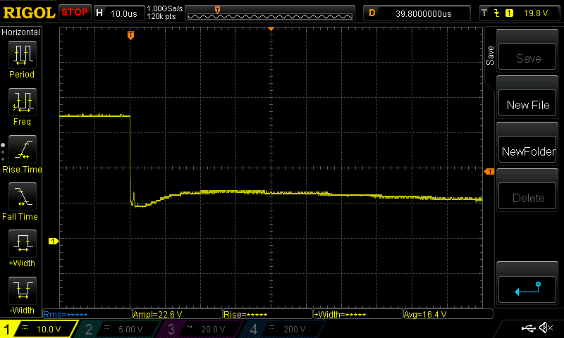 at 1us/div we can see the little bump which seems to always be there 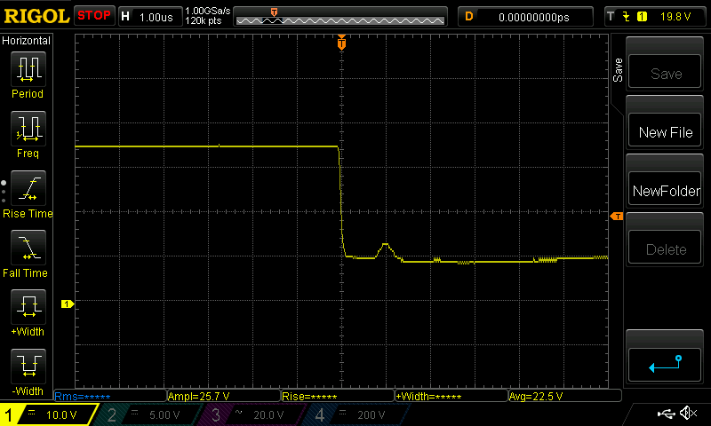 now I give it 22V on the gate, 35.4V on the big cap 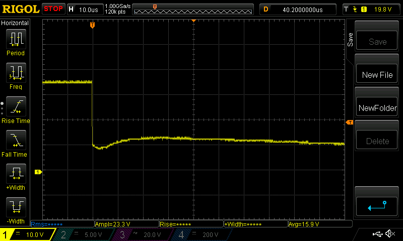 and then I go to 40.5V on the big cap and it blows. Not very interesting voltage capture this but it blew just the same. 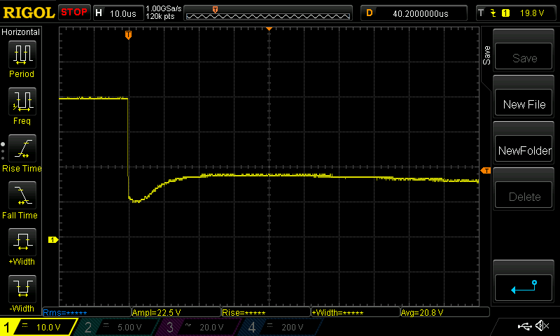 These FETs don't cost much and I think it would be fun for others to have a go. I solder the FET to the cap pins, run some thin hookup wire to the Gate and Drain, with a 1KR to pull it down. I did not bother with any small cap to help speed up the Gate voltage drive. I find it interesting that it blew at 40V this is 40 x 40 x 10,000 x 1e-6 x 0.5 Joules or 8 Joules A bit less than the 12.5 Joules at 50V wronger than a phone book full of wrong phone numbers |
||||
| wiseguy Guru Joined: 21/06/2018 Location: AustraliaPosts: 1156 |
Thanks for the update Peter. The graphs don't show the same peak after the falling edge for the last FET tests compared to the previous 2. Not sure why the peak was there but I guess also no surprise that the 20V gate voltage didnt make any difference to the peak which had vanished lol. So my theory remains just that, the latest test certainly didn't support it at all. In my capacitor experience which is mainly around Nichicon, United Chemi-con, Siemens and Panasonic, I am sure that I have killed very robust FETs with a lot less than 10,000uF so I am wondering about the internal impedance of the 10,000 CAPs. I have little faith in any Ali supplied capacitors and a whole lot less with their semiconductors which are often outright clever inferior forgeries masquerading as genuine parts. If at first you dont succeed, I suggest you avoid sky diving.... Cheers Mike |
||||