| Author |
Message |
Solar Mike
Guru

Joined: 08/02/2015
Location: New ZealandPosts: 1138 |
| Posted: 11:40am 25 May 2022 |
 Copy link to clipboard Copy link to clipboard |
 Print this post |
|
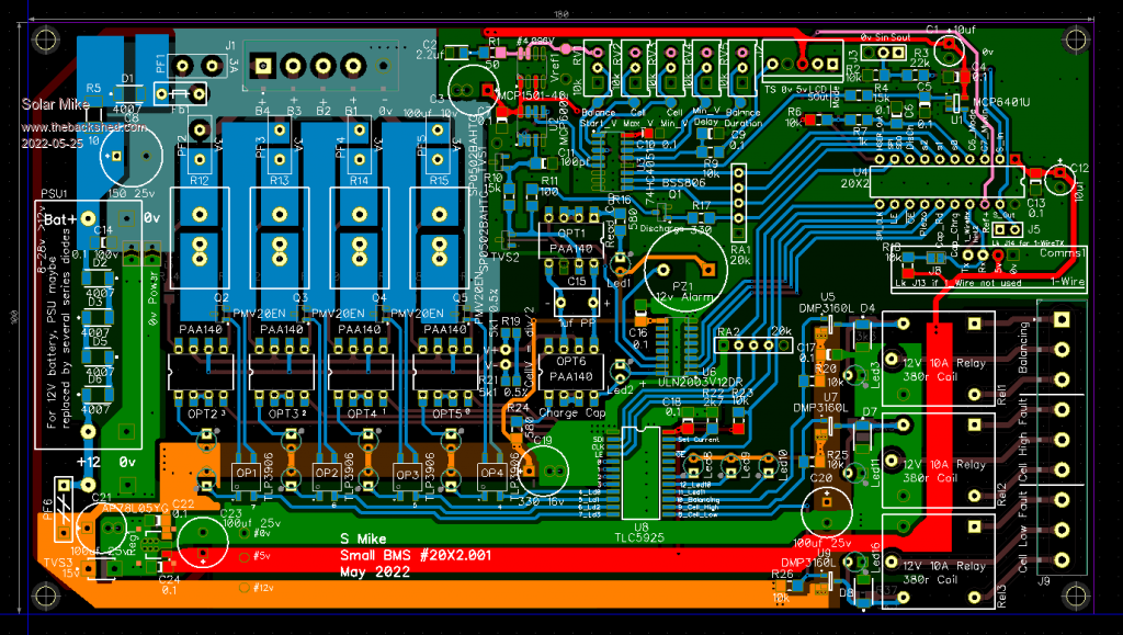
Have re-visited an older 4 cell BMS design, making it less complex and perhaps easier to build, with a smaller 100 x 180mm pcb.
A floating voltmeter concept is used with optimos switches charging a low leakage capacitor, that in turn is isolated from the battery for voltage measurement.
A serial input to 16 output constant current led driver is used to activate the switches and the IR-Voltage mosfet drivers for the cell dissipative loads (1-3A)
3 output relays can be used for further control of battery\PV contactors.
Picaxe 20X2 CPU controls everything.
As usual I dont have any schematic for this, but will draw one up to check it.
Cheers
Mike |
| |
Solar Mike
Guru

Joined: 08/02/2015
Location: New ZealandPosts: 1138 |
| Posted: 12:20am 01 Jun 2022 |
 Copy link to clipboard Copy link to clipboard |
 Print this post |
|
Schematic done, I have drawn up enough of it to check the pcb for errors, didn't locate any; it doesn't show numerous ceramic bypass caps nor all output terminal blocks and CPU programming wiring.
Will post gerber files here when I send them off to be made.
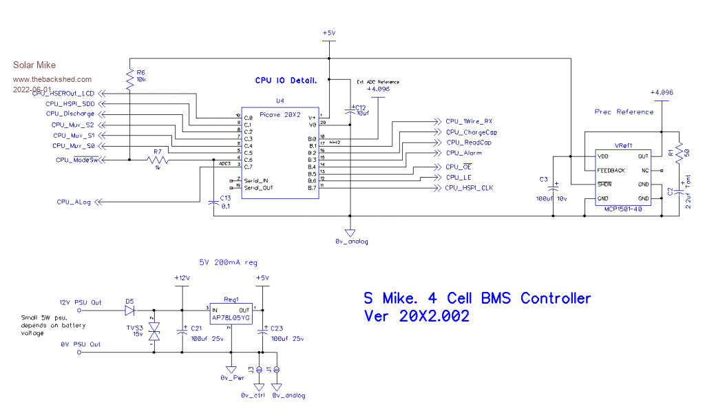
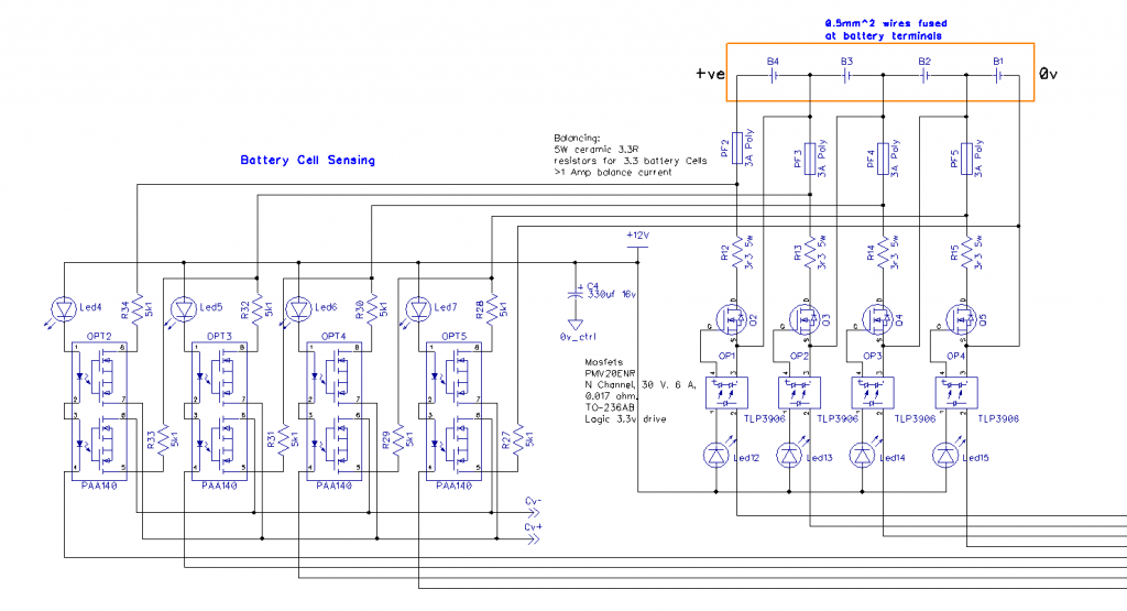
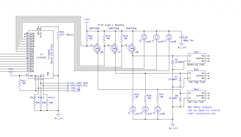
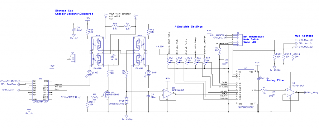
Brief on how it works:
To read a battery cell an optimos D.Pole switch is turned on to select the cell, then C15 is charged to the cell voltage by turning on OPT6; switches are all turned off leaving C15 floating; OPT1 is turned on and input to buffer U2.
CPU measures C15 voltage via the 8 input analog switch U3 input X5.
C15 is then discharged by Q1 and OPT1 is turned off.
Repeat for next battery cell.
If a cell reaches its balancing voltage as set by Pot. RV1, then a load can be switched across it, current being determined by the 10w ceramic resistors RV12-15. The voltage generating isolated mosfet drivers TLP3906 control the load mosfets.
During the voltage measurement phase any cell loads are turned off to prevent voltage drops in the balancing wires affect the readings.
A constant current LED serial input LED driver sets the led drive currents for all switches and also allows control of a few output relays.
This simple cut down design isn't extendable as its purely for a number of 4 cell Lifepo4 12V batteries we have out in the field.
I would quite like to make one using regenerative loads, perhaps using a small ringing choke inverter as the cell load feeding back into the battery bank; this would allow higher loads and less heat generation.... Another future project
Cheers
Mike |
| |
Solar Mike
Guru

Joined: 08/02/2015
Location: New ZealandPosts: 1138 |
| Posted: 05:29am 13 Jun 2022 |
 Copy link to clipboard Copy link to clipboard |
 Print this post |
|
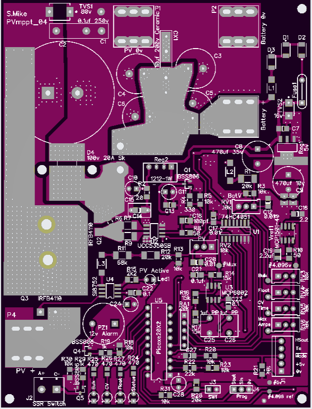
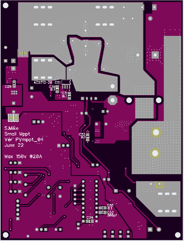
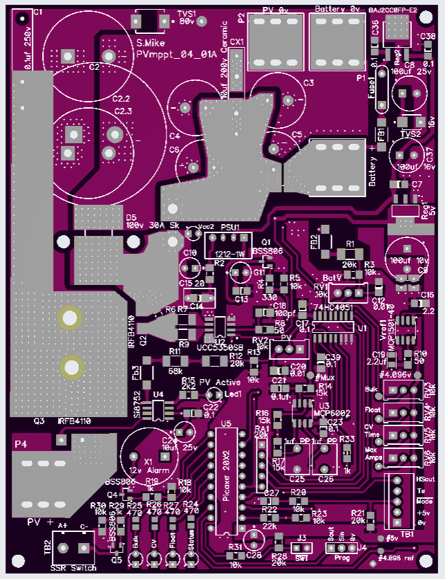
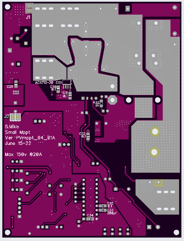
Here is the 12volt Mppt charge controller that goes with this 4 cell BMS, I wanted something small that can be used with PV voltages from 21 - 100 volt range and 10 -20 amps charge current. Most of the PV panels out in the field are mppt of 31volts and about 9 amps max, so this controller will work with most common size small single panels.
Of course this can be used for other battery voltages, mainly set by the power devices used, max pcb track spacing is 1.2mm, so limited to 100 volts odd input.
Will have to draw up a schematic for it.
PCB 138 x 105mm:
Cheers
Mike |
| |
Solar Mike
Guru

Joined: 08/02/2015
Location: New ZealandPosts: 1138 |
| Posted: 12:18pm 16 Jun 2022 |
 Copy link to clipboard Copy link to clipboard |
 Print this post |
|
Have drawn up a schematic for the 12V charge controller, in doing so a few modifications (improvements) have been made; main one being now using a low drop out (300mV) LDO 12v regulator chip for the main 12v supply. As the design will also be used on a few 12V lead gel cells, their voltage will vary more than the Lifepo4 batteries.
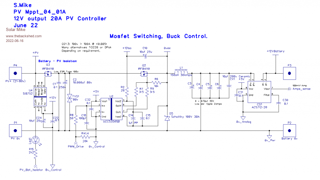
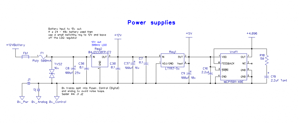
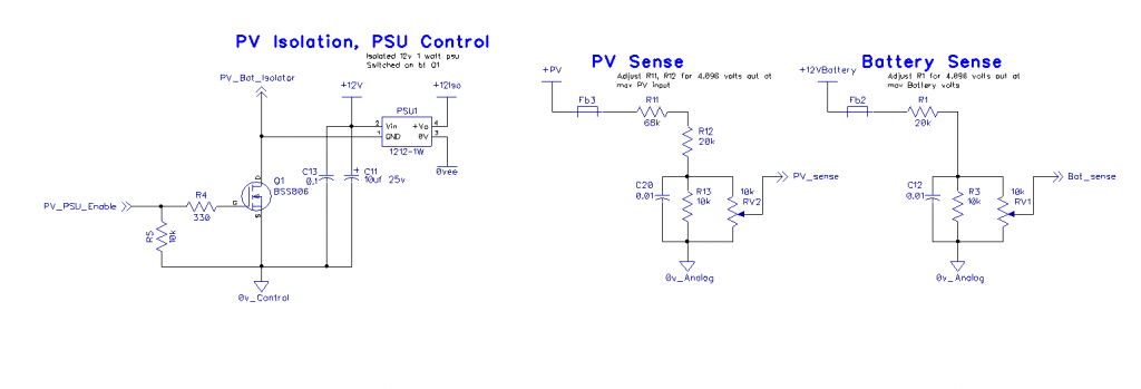
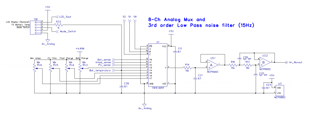
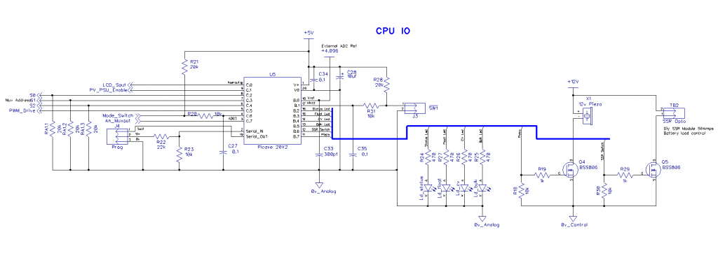
PCB 105 x 138mm:
Will do some more checks and post the gerbers when I send the boards off to be made.
Cheers
Mike |
| |
Solar Mike
Guru

Joined: 08/02/2015
Location: New ZealandPosts: 1138 |
| Posted: 09:43am 11 Jul 2022 |
 Copy link to clipboard Copy link to clipboard |
 Print this post |
|
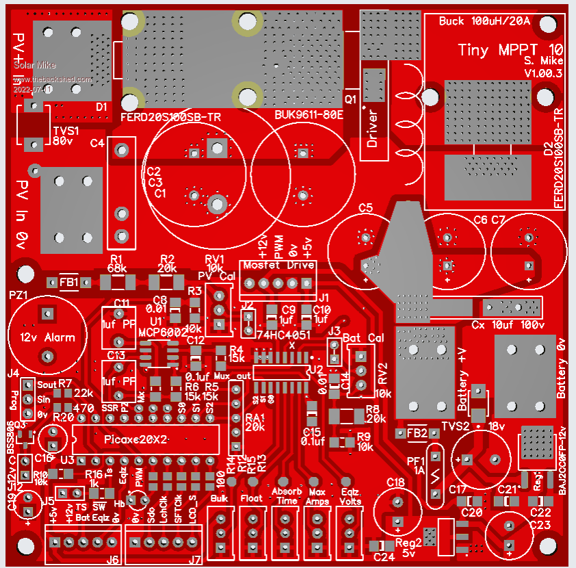
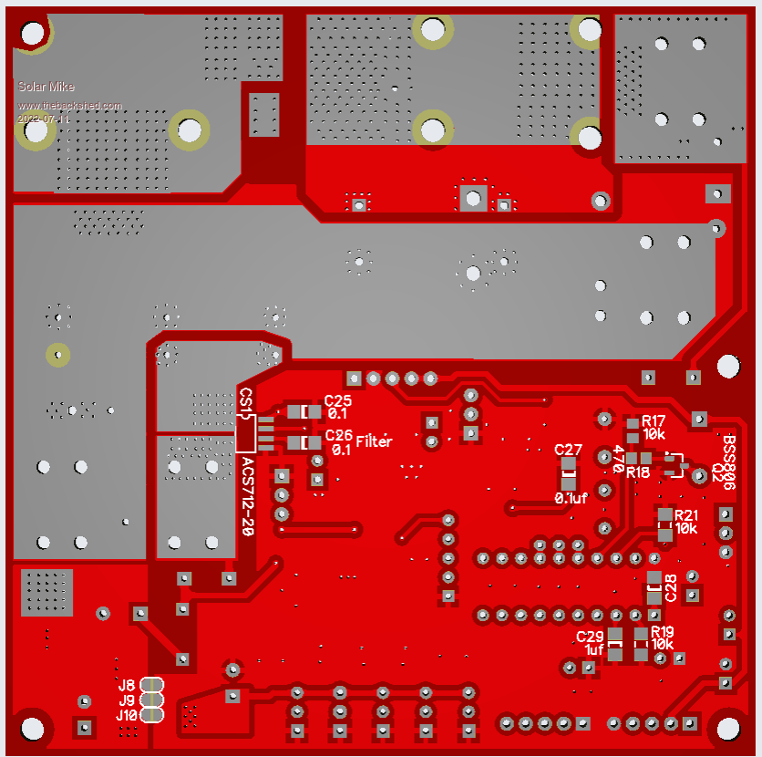
I require an even smaller MPPT board for 6 projects coming up, that require a small trickle charger max 10 amps, 12V battery (lead acid or Lifepo4) and 80 volts input. Have managed to do this based on the similar circuit in the above posts, simplified somewhat, all fitting on a 100 x 100mm pcb.
I have used semiconductors that are still available and with currents up to 10A a heatsink shouldn't be required. Based on previous designs and the number of input electro's fitted to the board, 20 amps would be the limit, requiring a larger buck inductor that won't fit on the pcb. The PCB edge can be mounted on an insulator (silpad) and bolted to an aluminum right angle heatsink if required.
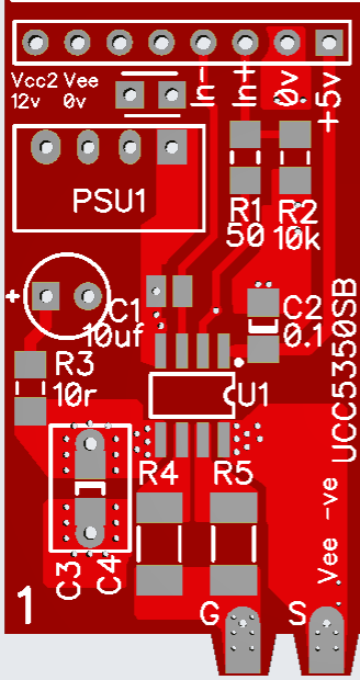
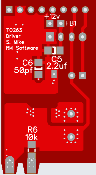
Its gets tricky with the buck mosfet driver to get an optimum layout on a small main board, so have moved the driver chip + isolated 12V-12V psu to a separate 40 x 21 mm pcb; this solders direct to the mosfet pins. They can be daisy chained to multiple devices, sharing the one 12v psu.
Another optional small pcb serially driven has the charge status leds, this mounts under the front panel, doing this now.
Main PCB 100 x 100mm:
Driver:
Cheers
Mike |
| |

