|

|
Forum Index : Electronics : About High Side Mosfets
| Author | Message | ||||
| InPhase Senior Member Joined: 15/12/2020 Location: United StatesPosts: 178 |
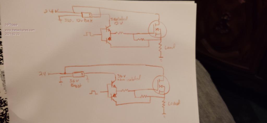
I have a load I need to switch on the high side. I have lots of N-channel FETs, so that's what I'll use. I won't be using a gate driver IC because it really isn't that complex or high speed. I don't have any isolated buck converters handy, but I do have some non-isolated boost converters. I have attached a pic showing my basic circuit with both buck and boost configurations. The second pic is how I'd like to do it because of what I have on hand. I have breadboarded it, and it works very good. The Vgs is 12 volts and according to my scope never spikes beyond 14 volts when switch rapidly. Everyone uses gate drivers or isolated buck converters to drive a high side FET. I have seen no one using a boost converter in this way. Why not? What is the drawback? Electrically, putting an isolated buck converter output in series with the supply voltage seems to be equivalent to a single non isolated boost converter. Am I wrong?  |
||||
| oreo Regular Member Joined: 11/12/2020 Location: CanadaPosts: 49 |
Both circuits look good to me. The only disadvantage I can see to the boost converter is that it would need to deliver 3x more power than the buck and buck converters seem to be more common. Power levels are so low here and you have the boost converter in hand. Greg |
||||
| mab1 Senior Member Joined: 10/02/2015 Location: United KingdomPosts: 209 |
errr.. is the on/off control pulse/signal isolated from the 24v battery? If not, where is it, voltagewise, relative to the 24v? |
||||
| InPhase Senior Member Joined: 15/12/2020 Location: United StatesPosts: 178 |
Can you elaborate on that some more? |
||||
| InPhase Senior Member Joined: 15/12/2020 Location: United StatesPosts: 178 |
It comes from the common-emitter connected output of an optocoupler supplied with 12 volts, all the voltages in the setup are referenced to a common ground. So there is a 12 volt control output, a 24 volt power supply source, and a boost converter at 36 volts. |
||||
| Warpspeed Guru Joined: 09/08/2007 Location: AustraliaPosts: 4406 |
I can see all sorts of problems with either circuit. There will always be either +24v or +36v on the gate, so the load can never be completely turned off. If the output is at zero volts, which it will be when initially powered up, placing +36v on the gate might easily pop the mosfet. If you have to do high side switching with an N channel device, and you don't need a fast switching speed, and you want simplicity and total isolation, check out the photovoltaic gate driver chips. These use a led to light up a little mini solar panel inside the chip to generate a +12v fully isolated gate voltage. These things are S L O W to turn either on or off, but can sometimes be very useful. https://www.mouser.com/pdfdocs/PanasonicPhotomosRelayPhotovoltaicMOSFETDriver.PDF Cheers, Tony. |
||||
| poida Guru Joined: 02/02/2017 Location: AustraliaPosts: 1418 |
how long does this job need to be done? If only for a month or something, how about a TLP250 or other optocoupler and a 9V battery? wronger than a phone book full of wrong phone numbers |
||||
| InPhase Senior Member Joined: 15/12/2020 Location: United StatesPosts: 178 |
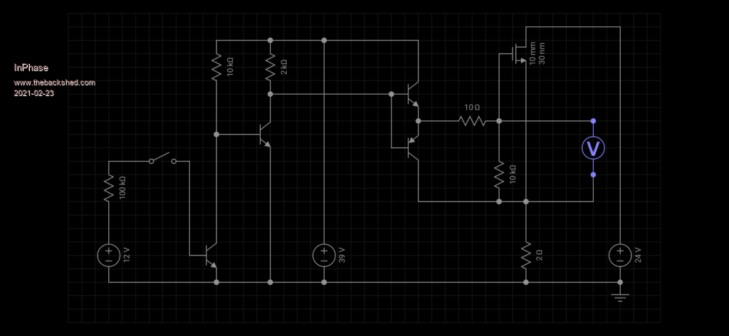
Thanks Tony. I see there is a fundamental gap in my knowledge of how this all works. I have measured the voltages on the breadboard. The circuit does indeed work, but as I increased the load, the FETs did get hot and I observed they didn't go all the way off on the scope. I never saw the Vgs go above 14 volts. I see now how the 36 volts finds its way around. The problem with new components like the PV optocoupler you linked is that I don't have any now. I can get some, but I'm a lot ADHD. So in the mean time until something better comes along, I want to attempt to bodge this all with what I have. I've simulated a new circuit that seems to work 100%. Before I breadboard it, I'll post the pic of the sim. I've tweaked the boost voltage to compensate for the simulation variables. Let me know what issues, besides the ridiculous parts count, you see. The 12 volt supply and toggle switch are how I represent the control voltage.  |
||||
| Warpspeed Guru Joined: 09/08/2007 Location: AustraliaPosts: 4406 |
That looks much better. Cheers, Tony. |
||||