|

|
Forum Index : Electronics : Calculate Transformer Inductance
| Author | Message | ||||
| InPhase Senior Member Joined: 15/12/2020 Location: United StatesPosts: 178 |
I have a toroidal isolation transformer. Just for fun, I wanted to calculate the inductance of the primary using measured values. So the DC resistance of the primary is 0.2 ohms. At 120 volts 60 Hz, the idle current current is 0.05 amps. Am I right in thinking that the impedance of the primary is the DC resistance + inductive reactance and by knowing these I should be able to algebraically solve for the inductance? 0.05 amps at 120 volts means the primary impedance is about 2400 ohms. Since XL is 2(pi)fL, then L must be 6.36 H... Yes? |
||||
| Warpspeed Guru Joined: 09/08/2007 Location: AustraliaPosts: 4406 |
Its not that simple, unfortunately. The combined impedance you are measuring (the idle current) is made up of two components, the inductive component as you would expect, plus a resistive component which is produced by eddy current losses in the core material. The eddy current loss is resistive, and in phase with the primary voltage. The effect is something like a highly resistive shorted turn. The inductive component will be a pure inductance that has the current lagging by ninety degrees. The resistance of the wire itself has little or no effect at 50mA. It only starts to become significant under higher transformer loading conditions. Only practical way to sort this mess out is with an impedance bridge, which will have two separate adjustments. One for the inductive component, the other for the resistive loss component. By tweaking both controls alternately for the deepest null, its then possible to read off the true inductance. Its also very important to make this measurement at, or very close to the normal operating frequency of the transformer, which should be well below any natural transformer resonances. Cheers, Tony. |
||||
| iannez Newbie Joined: 05/07/2019 Location: ItalyPosts: 23 |
Hi InPhase, the DC measurement is the resistance of the winding. live measurement with open secondary is the reactance of the primary. look here: https://sound-au.com/xfmr.htm point 4.1 Inductance solve equation for L: L = V / (I x 2PI x f) = 6.3694H interesting site with many true examples. also talks about isolation transformers somewhere. Ciao! A. Edited 2021-02-12 07:07 by iannez Cheers, Angelo |
||||
| InPhase Senior Member Joined: 15/12/2020 Location: United StatesPosts: 178 |
Thanks Tony. I knew it couldn't be that simple. But I have more questions now. What portion of that 50 mA x 120 V = 6 watts is being spent on eddy currents and what portion of it is dissipated across the theoretical E/XL? |
||||
| Warpspeed Guru Joined: 09/08/2007 Location: AustraliaPosts: 4406 |
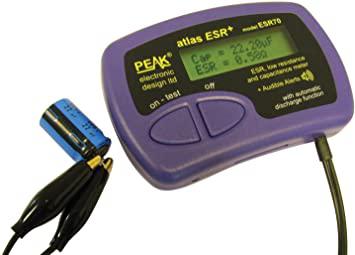
There are a few different approaches to the problem, depending on what test equipment you have available. Use a commercial impedance measurement bridge, which is designed to do exactly what you want. It will give you vales for L and R equivalent directly. A simpler way to just measure the inductance would be to resonate the primary with a known capacitance, and measure the resultant resonant frequency. The problem with the resonance method will be that the resistive loss component might be high enough to seriously reduce the Q to the point that its very difficult to define an exact maximum peak, of what might be a very low wide spread out hump. Another way would be to measure the phase and amplitude difference between the applied voltage, and the resultant current. Then with some vector number crunching come up with a resultant R and L worked out by some clever software.  This is more commonly done to measure the equivalent series resistance (ESR) of a capacitor, but a similar measurement method could separate out inductance and resistance of a lossy winding. But really, the inductance of a transformer, and the magnetising current will both vary quite widely depending on the applied voltage, so its not something that is easy to pin down to a precise meaningful figure. Cheers, Tony. |
||||
| Gizmo Admin Group Joined: 05/06/2004 Location: AustraliaPosts: 5078 |
I remember as a teenager playing around with inductors. I had limited resources, a 12vac supply and my multimeter was a toy with no AC amps feature. From memory, to work out the inductor value(L) , I would connect the inductor with a series resistor, pass 12v 50Hz AC through them both, and measure the voltage across both the resistor and the inductor. With the resistor voltage and resistance ohm value I used I=V/R to get the circuit current. Then use the inductor voltage and circuit current to work out its resistance at 50Hz ( impedance X ). Then used this value and 50Hz to get the inductance using L = X/(2*Pi*f) ( I think ). I remember the resistor would get hot so I had to be quick. As 50Hz was my only AC supply, the technique was only good for large inductors. You can use the same technique for unknown capacitors. Glenn The best time to plant a tree was twenty years ago, the second best time is right now. JAQ |
||||