
|

|
Forum Index : Electronics : cheap 2A boost dc-dc converters
| Author | Message | ||||
| poida Guru Joined: 02/02/2017 Location: AustraliaPosts: 1418 |
So I saw on Ali some new (to me) boost converters... 5-32V IN, 5-55V out, 2A for $2.50 US plus $0.68US postage . they use the XL6009 converter chip. XL6009-DC-DC-Converter-Datasheet.pdf 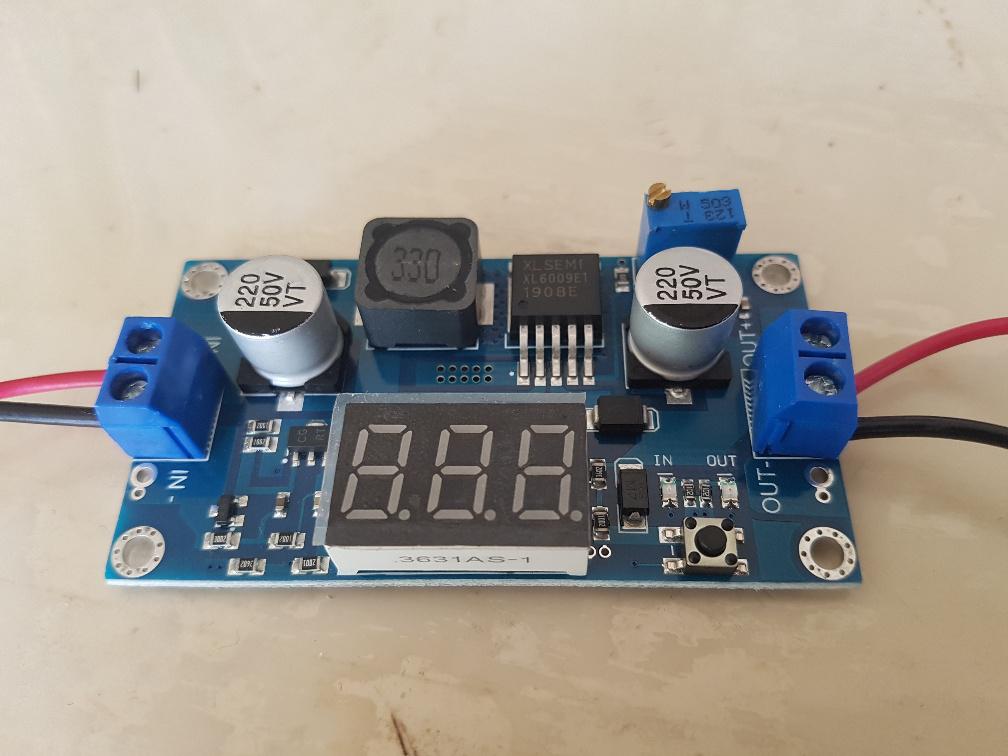 So I got a couple and the first thing to do is to test them. These are promoted to be good for laptop supplies, so I tested at 18V and 25V output both with 12.7V input. You set the output voltage via a multi turn trimpot. As supplied 18.0V @ 0Amps 18.2V @ 0.5A load 17.0V @ 1.0A 16.2V @ 1.5A 15.4V @ 2.0A 14.9V @ 2.5A (no smoke) and at 25V output 25.0V @ 0A 26.7V @ 0.5A 29.0V @ 1.0A 26.3V @ 1.5A 20.2V @ 2.0A This is crap regulation. I put a probe on the output and here it is at 1.0A at 25V output. Yellow is output voltage, AC coupled, 0.5V/div Light Blue is the switch node showing the boost output pin of the inductor which clearly shows the switching frequency and gives me something to trigger off. 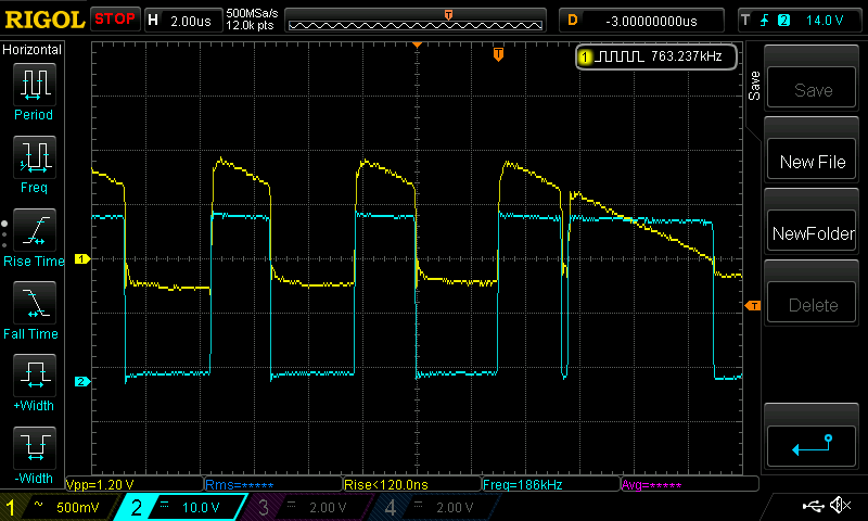 Not real good. Both samples performed the same. I thought the output cap was not filtering well enough so I put a bigger one on it. 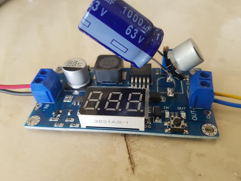 and regulation improved somewhat. 18.0V @ 0A 18.0V @ 0.5A 18.0V @ 1.0A 17.9V @ 1.5A 17.4V @ 2.0A 25.0V @ 0A 25.3V @ 0.5A 25.1V @ 1.0A 24.2V @ 1.5A 20.9V @ 2.0A But still not good enough, really. here is the output ripple now. 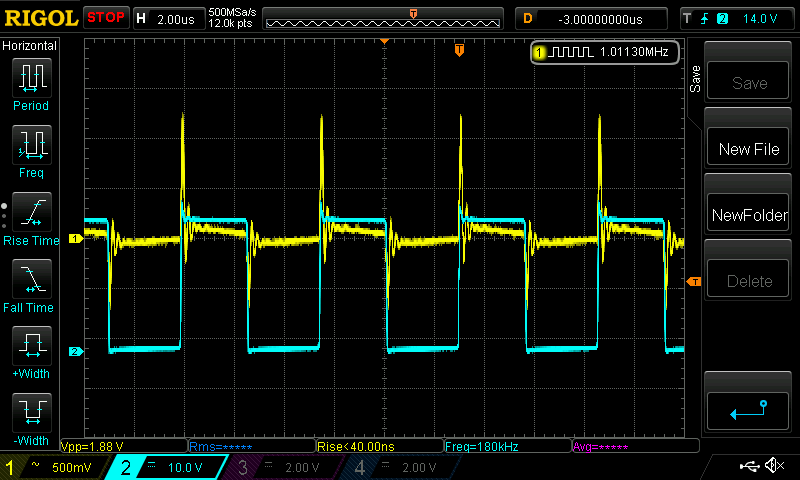 That is a huge change. No wonder voltage regulation was crap with the original output filter capacitor. An old and dusty boost converter such as below does +/- 0.04V regulation at 18V over 0 - 2A and +/- 0.1V at 25V over 0 - 2A, all with 12.7V input 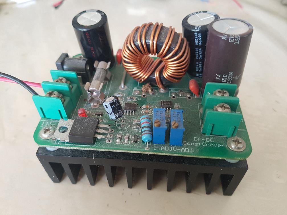 and a synchronous buck/boost costing a lot more is very good +/- 0.05V at 18V and +/- 0.02V at 25V. This converter is efficient. at 25V, 2A out, it's 94% 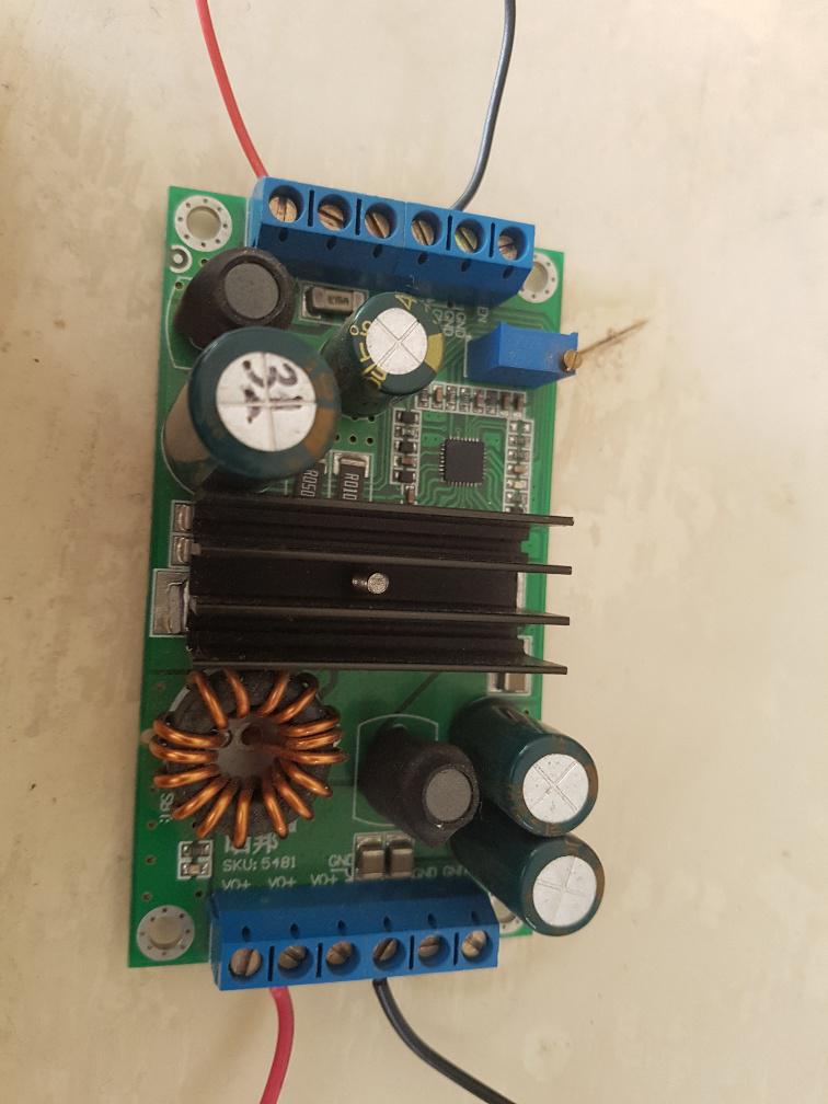 wronger than a phone book full of wrong phone numbers |
||||
| mikeb Senior Member Joined: 10/04/2016 Location: AustraliaPosts: 173 |
Try replacing both caps with low ESR types. Switching frequency of these types of converters is usually in the 100's of kHz. There is a reason for the very low cost.  Regards, Mike B. There are 10 kinds of people in the world. Those that understand binary and those that don't. |
||||
| poida Guru Joined: 02/02/2017 Location: AustraliaPosts: 1418 |
oh, for sure, Mike. I was wondering what you get for the $ or two. Looking at for instance the LM2588 converter chip, TI's example circuit has a 1,000uF on the output, 4x larger and undoubtedly about 10x better in ESR etc since it's a Nichicon 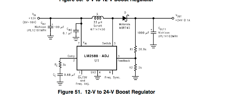 here is a look at the voltage feedback at pin 3 on the XL6009 at 12.7V in, 25V @1A out. Purple is feedback voltage, needs to be 1.25V. I put the White cursor on 1.25V Yellow is output voltage, AC coupled Light Blue is switch node. 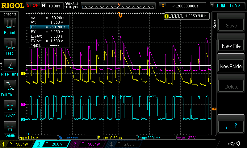 This is so bad I can't even explain how it works at all. The point of this post is to show what you can get for the pocket change when it's made of pure Chinesium. I have no need to make these converters work for any project. It's something to spend time doing in the lockdown. wronger than a phone book full of wrong phone numbers |
||||
Grogster Admin Group Joined: 31/12/2012 Location: New ZealandPosts: 9307 |
Very useful posts - thanks.  I have never used that particular module, but I have seen them on eBay or AliExpress, and they are only about $2 or so I think, complete with the LED display - something has to give!  What model Rigol do you have? I am looking at a couple of models. Any particular reason you got the one you have? So many to choose from..... NONE of those buck/boost or SEPIC modules will ever be able to deliver the current they claim as they are. They all need a heatsink for the higher output loads. Generally up to 1A or so, they are OK, but more then that, and they do tend to get really rather hot so need heatsinking I have found. Unless the load current is sporadic. I have used LM2596 buck modules without a heatsink for thermal printers that suck 1.5A to 2A when printing, but as that is a low duty-cycle, they happily do those kinds of loads, just not at 100% duty.  Even when I use those modules, I still tend to add a bit of extra input and output decoupling on the host PCB that carries them for exactly the same reasons as you have stated. If you have one of the LM2596 buck modules, I would be interested to see what your Rigol makes of the output ripple on those, as I have used a few of those for things, but they seem to work OK. Quite possibly only cos I add the extra input/output caps. I wonder how they can even make the CLONES of these for the price they sell them for. I suspect the chip they are using is either a factory reject(which might explain why the reference/FB(purple) voltage is all over the place), or it is some other copy of something else, labelled as something it is not. Smoke makes things work. When the smoke gets out, it stops! |
||||
| poida Guru Joined: 02/02/2017 Location: AustraliaPosts: 1418 |
Glad this is of interest. The scope is a Rigol DS1054Z. I find it more useful than anything I can imagine for the inverter/charge controller/PS learning. You can still hack them to be 100Mhz and with full memory and extra triggers. 4 channels is a must. 100MHz is enough. No need to go higher since even at 50-100Mhz you need to use careful probe technique that dispenses with the little alligator clip earth leads. (I got mine when Rigol released it with a poorly performing PLL that drives the ADC so there was a bucketload of jitter in the displayed traces. This was fixed with a firmware update. About 2014 or something when $1AUD = $1US) The voltage feedback is connected to the output terminals, then fed into a trimpot. So Vfb = output x some_factor with zero low pass filtering. All it needs is an output with far less ripple. It's likely the output cap is about 2c in cost and so has a huge ESR. I checked it's value at 100Hz with the LCR meter and it's 220uF as marked. At 10kHz it dropped to about 3uF As far as cheap/dysfunctional clones go, the controller is an XL6009, made in China I think. What is quite possible is the XL6009 spec sheet is just thrown together and the circuits and component values may as well be for a NASA lunar probe PS that uses TI and LT parts. From what I see with the switching and control - when fitted with the extra cap - the chip seems to work well. I think if it's given a low ripple feedback, it will perform much better again. wronger than a phone book full of wrong phone numbers |
||||
| Warpspeed Guru Joined: 09/08/2007 Location: AustraliaPosts: 4406 |
I also bought a DS1054Z after Peters glowing recommendations. Best thing I have done in a very long time. Its a truly amazing bit of kit. Cheers, Tony. |
||||
| disco4now Guru Joined: 18/12/2014 Location: AustraliaPosts: 896 |
I also have a DS1054Z, a couple of years now. I thought @poida's must have been a much more powerful thing because mine could not do anything like what his was doing. But it is the same and I have learned a lot and managed to reproduce many of the captures shown building the MPPT solar controller. Gerry Latest F4 Latest H7 |
||||
| Warpspeed Guru Joined: 09/08/2007 Location: AustraliaPosts: 4406 |
Yes the DS1054Z has a vast range of features that can be very difficult to learn and use at first. I think it takes a very long time to get to get the best from it. But even if most of the features are never exploited to the full, its still a very nice oscilloscope. Cheers, Tony. |
||||