
|

|
Forum Index : Electronics : Split system A/C voltage and current waveforms
| Author | Message | ||||
| poida Guru Joined: 02/02/2017 Location: AustraliaPosts: 1418 |
I have completed the installation of 3 new Mitsubishi A/C units. All are 2.5kW current model inverter drive types with a rated input of 550W cooling and 660W heating. RenewableMark has shown gross AC voltage distortions on the solar inverter output when the AC in his home is run. I wanted to see how my units will go. I applied 240V AC STREET power to a unit via the voltage and current sensor box I built ages ago. (power factor and Watts measured with a very good power meter - Power Mate) Yellow is street voltage Light Blue is current. 4W on standby as the compressor starts up, more and more power is drawn. We see this shape only for 10 seconds or so. 500W: 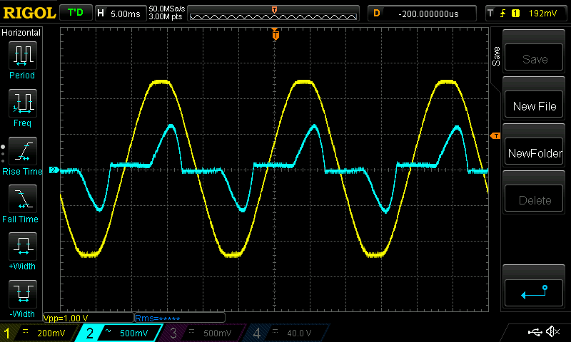 860W PF is 0.910 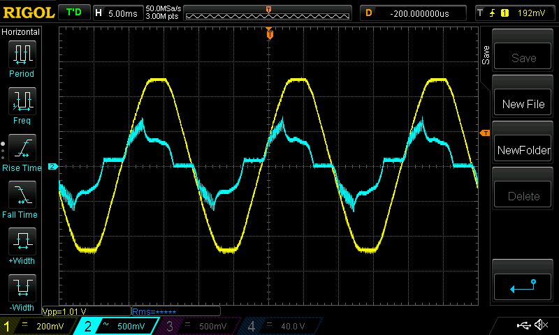 922W (241V, 4.2A) PF is 0.92 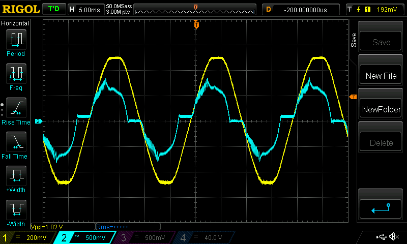 Next I hooked it up to the 3kW home built inverter. The AC was running near flat out heating the room. 1171W 1282VA PF is 0.92 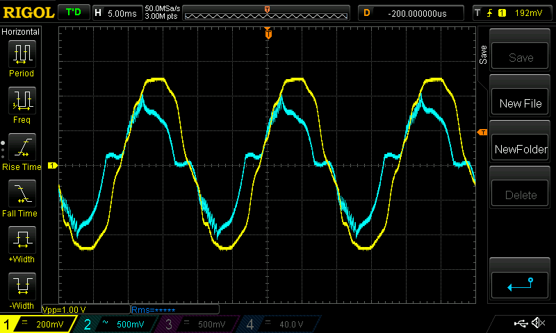 Notice the distorted AC voltage waveform. It seems to me the inverter is supplying a fairly stiff (low impedence) current to the load. OF course the street supply is very stiff and can handle large non-linear loads and keep looking good. But I think the inverter can dive at least one of these A/C units with capacity to spare. wronger than a phone book full of wrong phone numbers |
||||
| Davo99 Guru Joined: 03/06/2019 Location: AustraliaPosts: 1578 |
Most of these inverter AC's are 3 Phase motors with their own own single to 3 phase inverter built in. This is because the compressors are variable speed to suit the load. Some of the distortions may be from the inbuilt inverter itself. I guess they are only as good ( and cheap) as they need to be. |
||||
renewableMark Guru Joined: 09/12/2017 Location: AustraliaPosts: 1678 |
Ahahahahahahahahaha, not many of us have looked at the wave when AC is run on an off grid unit. That looks pretty good actually, my unit is a lot bigger and stuffed the wave more than that. On flat out and eco setting it was ok though. Cheers Caveman Mark Off grid eastern Melb |
||||
| poida Guru Joined: 02/02/2017 Location: AustraliaPosts: 1418 |
I would say all modern inverter type ACs use the single to 3 phase design. Speed control of the compressor is the main requirement and it is best met with a 3 phase motor and (probably) a vector drive. The compressor is where most of the power is consumed so that is where most efficiency gains can be found. wronger than a phone book full of wrong phone numbers |
||||
| Haxby Guru Joined: 07/07/2008 Location: AustraliaPosts: 423 |
Poida, Do you have any details on the voltage/current sensor box? |
||||
| BenandAmber Guru Joined: 16/02/2019 Location: United StatesPosts: 961 |
 There is a guy on youtube that runs a 3 phase split ac outside unit with straight solar panels no battery no inverter He uses a vfd that has dc input I can find the name if anyone is interested Thanks for sharing info on these split units It seems to be the future of off grid ac These 3 phase out side units can be found cheap some times and do have the benefit of changing the speed of compressor Have a blessed day Edited 2020-08-18 04:48 by BenandAmber be warned i am good parrot but Dumber than a box of rocks |
||||
| poida Guru Joined: 02/02/2017 Location: AustraliaPosts: 1418 |
yup. I use a LEM current sensor for current, so it needs an external 5V supply. The AC voltage comes from a voltage transformer ripped out of an Aerosharp. Both outputs are isolated, well in excess of 2kV. The IEC input jack has a 10 Amp fuse. I use an IEC lead to supply it and hook up the load to the 3 pin socket. It's really accurate and has good frequency response. 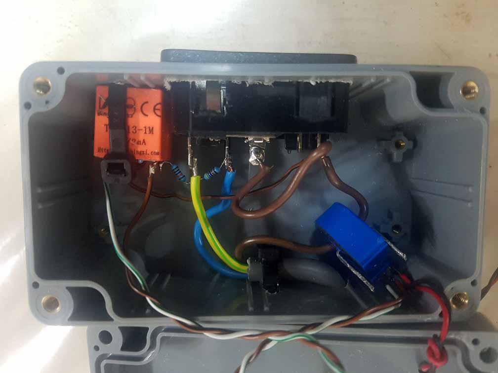 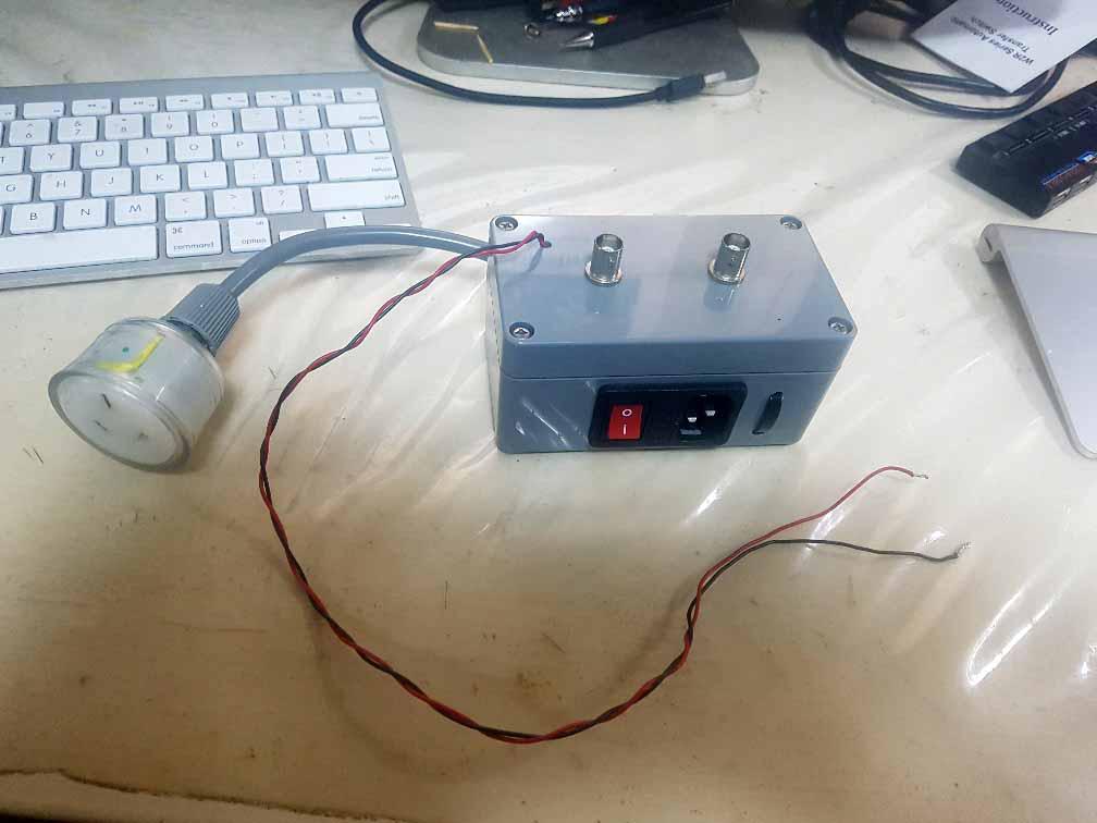 wronger than a phone book full of wrong phone numbers |
||||
| Warpspeed Guru Joined: 09/08/2007 Location: AustraliaPosts: 4406 |
A very handy gadget to have Peter. Pretty easy to make too. Cheers, Tony. |
||||
| poida Guru Joined: 02/02/2017 Location: AustraliaPosts: 1418 |
Just for fun I had a look at the voltage and current with two power supplies. One is a monster. It uses the 35kg IE transformer from an old CIG electrolysis supply. It can do about 35Amps at 50 or 60V all day so it's rated at about 1500W I use the centre tap for ground and two AC outputs into two diodes in series each. Then into 5 x 8,000 uF 75V Ducon capacitors. They were made in Australia. I can just manage to carry it around. Just. The other is a 2000W switchmode off line supply from Eltek. It's weight is 2 kg. It is about as heavy as a large paperback book and can be carried with one hand. First we see the 35kg monster. 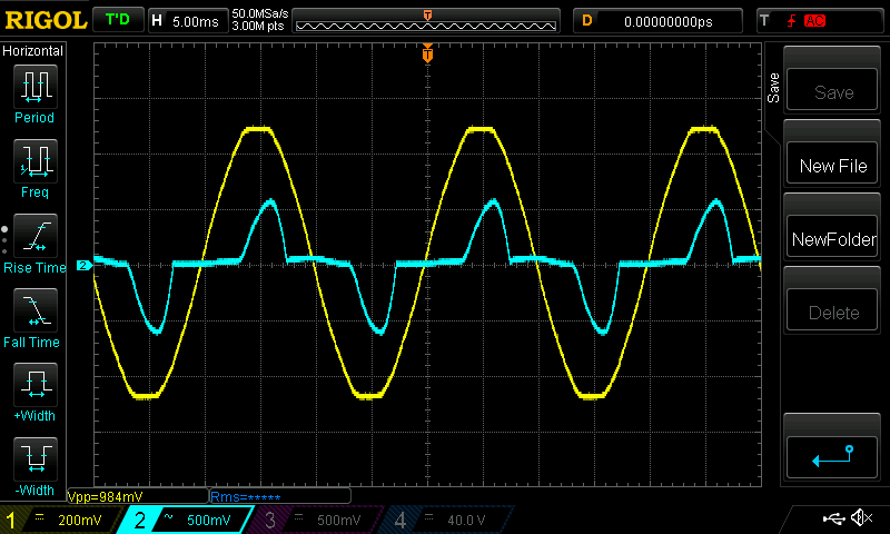 The short current pulses are when the diodes conduct the AC, when the output voltage is less than the input voltage. This is typical of unregulated linear supplies. The power factor was something like 0.7 or 0.8 when drawing about 700W Next is the Eltek. 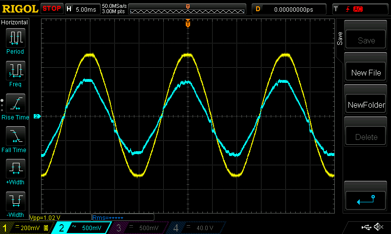 This is drawing power throughout the AC waveform. The power factor is 0.98 and in this test I was drawing about 1700W It probably has a carefully designed power factor correction system on the AC input that powers the line voltage bulk capacitors which then drive the switchmode converter. I never thought I would see PFC perform this well. The closer a device gets to a power factor of 1.0 the better it is for the system supplying this power. Also the power supply runs at more steady power loads. wronger than a phone book full of wrong phone numbers |
||||
| Haxby Guru Joined: 07/07/2008 Location: AustraliaPosts: 423 |
Thanks Poida. Might make one myself! What are the resistors in series with the transformer doing? |
||||
| poida Guru Joined: 02/02/2017 Location: AustraliaPosts: 1418 |
It's to reduce the current to the required value. The device is limited to 2mA input. voltage transformer PCB K1080274588.pdf I forget what I chose, I suppose I aimed for 1V p/p output or something like that. wronger than a phone book full of wrong phone numbers |
||||
| wiseguy Guru Joined: 21/06/2018 Location: AustraliaPosts: 1156 |
It looks like maybe a 100K and 47K resistor in series with the primary of the voltage transformer, 240V yields ~ 1.63mA well within the 2.0mA maximum. The manufacturer specifies a maximum load of 250R - so with a 2.0mA maximum the highest achievable secondary voltage would be 0.5V. With the above 1.63mA and a 150R secondary termination would yield ~0.24V or 1000:1 @ less than 2% error. Whilst a higher secondary resistor may still work, the linearity/accuracy/phase shift etc must get compromised. If you had a spare 240V to 5V little isolated converter handy you could power up the current sensor internally, removing the need for the external power supply. I like the simple project a lot, instead of setting up each time for independent current and voltage measurements and phasing them correctly its all set up and ready in a flash. Ok maybe not the best description for a mains device....... do take care! Edited 2020-08-20 01:19 by wiseguy If at first you dont succeed, I suggest you avoid sky diving.... Cheers Mike |
||||
renewableMark Guru Joined: 09/12/2017 Location: AustraliaPosts: 1678 |
Peter, with the second test you did was that A/C unit run from your inverter with it's DC input supplied by the EI trans and the eltek? Cheers Caveman Mark Off grid eastern Melb |
||||
| poida Guru Joined: 02/02/2017 Location: AustraliaPosts: 1418 |
The second test used the home inverter. 3kW toroid, Madness 6kW powerboard, nanoverter. During that test other loads on the inverter were present such as the iMac computer, the electronics bench equipment, many devices on standby, desk lamps etc. wronger than a phone book full of wrong phone numbers |
||||