
|

|
Forum Index : Electronics : Where can I find a STRL472 IC???
| Author | Message | ||||
Grogster Admin Group Joined: 31/12/2012 Location: New ZealandPosts: 9308 |
Hello all.  My Toshiba heat-pump went bang the other week, and I have not been able to use it since. As we are heading into winter, I needed to get this fixed, so I pulled the indoor unit to bits, removed the main-board, and found a STR-L472 Switchmode controller IC blown in half.  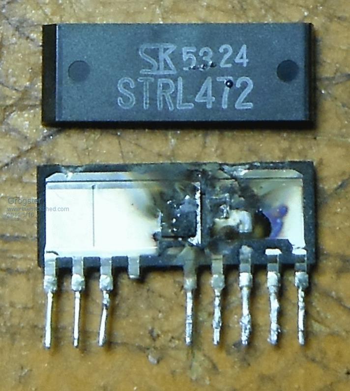 That would explain why the indoor unit is dead, and will not start. The only problem now seems to be where to find a replacement IC? They are all over eBay and AliExpress, but I suspect they are probably clones, and I really don't want to use one of those, I want a genuine one as it took about an hour to get this far into the indoor unit, so I don't want a cheap clone going bang soon after I reassemble it all.  Element14 don't know anything about it, Mouser don't know anything about it, but DigiKey does have a listing for it, but they don't have any and are not expecting any more till about the end of June. I don't really want to wait that long.....  Does anyone know another site I can perhaps get the genuine article from? Smoke makes things work. When the smoke gets out, it stops! |
||||
| Warpspeed Guru Joined: 09/08/2007 Location: AustraliaPosts: 4406 |
These are made by Sanken in Japan. Digikey Australia are listed as the Aussie Sanken agent, but they have zero stock and currently a 12 week back order. Sanken in Japan offer direct on line sales, that may be your best bet. http://www.semicon.sanken-ele.co.jp/en/sales/ Cheers, Tony. |
||||
| wiseguy Guru Joined: 21/06/2018 Location: AustraliaPosts: 1156 |
Have to laugh at first I thought it said heart pump ! The units on Ebay look identical to yours - personally I would buy one and try it and take the chance - if it works its a cheap fix. (Better still take Warps advice above and buy direct) First though (before powering up again) check the rectifier diode on the secondary is still ok and replace the secondary electrolytic capacitor regardless of appearance. For good measure also replace the small bootstrap/startup capacitor on the primary side. The main capacitor on the primary is rarely faulty in my experience but again replace it if in doubt - its cheap insurance. Thinking again and looking at the IC who knows what other parts got a big jolt - I would replace everything on the primary side except resistors that still measure their marked value, Theres only a dollar or two worth of parts there. Good Luck ! If at first you dont succeed, I suggest you avoid sky diving.... Cheers Mike |
||||
Grogster Admin Group Joined: 31/12/2012 Location: New ZealandPosts: 9308 |
Thanks chums.  I have ordered some, and I will also replace the parts suggested by Mike. I have also found an o/c half-watt or so 0.91R 5% resistor - R12 between pins 6 and 10 of IC1. I will replace this resistor too, naturally. When the heat-pump went bang, there was no apparent surge or anything, as I was using other things in the room at the time. It was working happily, then just made a loud crack noise - which I knew was not a good thing - and then never worked since. But my HT amp and computer in the same room kept on going no problems, so I am reasonably confident it was not a surge or spike that killed it, more likely that IC01 just failed. It probably runs hot like most of those chips tend to do. R12 may have gone o/c first, killing IC01 in the process, as R12 is actually cracked. Generally, carbon resistors take quite a bit of killing.  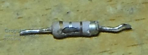 This tests as o/c, which is not good.  EDIT: Here is the basic PSU schematic from the 472 PDF: 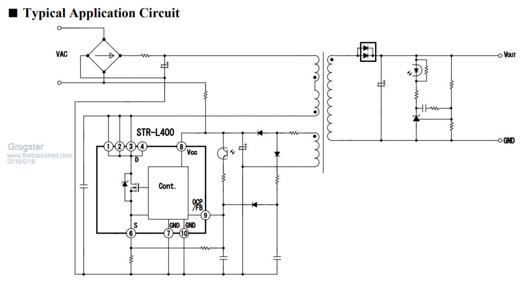 Although no parts are labelled here, you can see that R12 between pins 6 and 10, is what appears to be a little current-limiting resistor on the source of the internal MOSFET driver for the hot side. EDIT: Cannot find a 0.91R half-watt. This is an odd value.... I will have to use a 1R half-watt carbon instead. Hopefully, a few milliohms won't be THAT critical. Smoke makes things work. When the smoke gets out, it stops! |
||||
| wiseguy Guru Joined: 21/06/2018 Location: AustraliaPosts: 1156 |
The killing probably went like this. The FET died & shorted. Excess current went via pin 6 to ground (R12) went ouch and open circuited. The next path for the current was the resistor between 6 & 9 - or internally sourcing from pins 8 & 9 hence all the components being suspect. The output capacitor or rectifier diode are the most likely culprits that may be faulty and caused the bang or maybe the STRL400 just got bored... Those dull grey resistors that look like the one in your picture are usually wire wound and have a flame retardant coating. I would not use the carbon one as it will probably fail quickly. By all means use a smallish 1R WW (~1W) and trim it to 0.91R value with a 10R carbon film in parallel. Replace the opto-coupler, if the TL431 (output side reference) is faulty it will be the first one in the many thousands I have used and serviced! BTW the 1R would probably work fine without being trimmed, some engineers like exact values.... If at first you dont succeed, I suggest you avoid sky diving.... Cheers Mike |
||||
Grogster Admin Group Joined: 31/12/2012 Location: New ZealandPosts: 9308 |
You've done this before, haven't you!  Yes, I will replace ALL parts on the hot(primary) side - just to be sure. ...and also the secondary cap along with checking the diodes. Thanks for your posts and continued interest.  Smoke makes things work. When the smoke gets out, it stops! |
||||
Grogster Admin Group Joined: 31/12/2012 Location: New ZealandPosts: 9308 |
Just FYI, here are two shots of the main-board from the indoor unit: 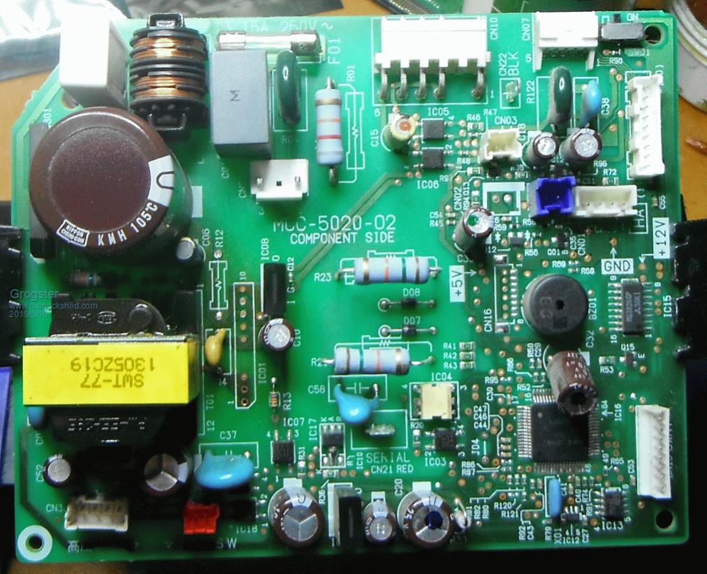 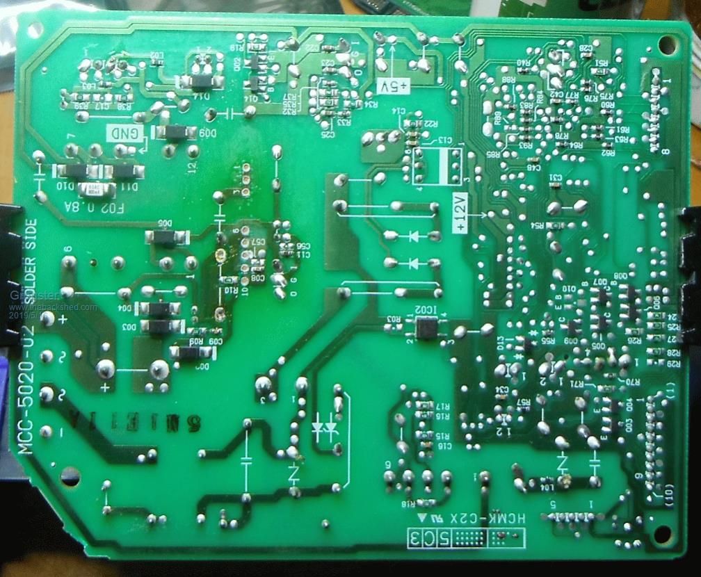 Does this board look familiar?  EDIT: Note the discolouration around IC01 that blew itself to bits. This suggests that at least at SOME point in its service life, it was running hot. Smoke makes things work. When the smoke gets out, it stops! |
||||
| wiseguy Guru Joined: 21/06/2018 Location: AustraliaPosts: 1156 |
Once or twice at least...... No not totally familiar - its one of many similar units though. Just edited my post - thanks for the picture - I hope you sort it out ! Check F02 is still intact and all those SMD diodes too. What is IC08 - is that the opto ?? If at first you dont succeed, I suggest you avoid sky diving.... Cheers Mike |
||||
Grogster Admin Group Joined: 31/12/2012 Location: New ZealandPosts: 9308 |
Howdy.  F02 is still intact. All diodes test as OK, although in the reverse-biased condition, there is still a reading as the test current is going back via the HF transformer to the other side of things and providing a circuit. I am happy enough that they are OK though without removing them entirely to test them out of circuit. I have ordered 4x 472 IC's with DHL from AliExpress, so that if I explode another one, I will have some spare ones. I intend to follow the Toshiba service manual and power the board with everything except the front panel disconnected, to see if it blinks at me(the LED) on power up, which would suggest it is reasonably happy again, before final reassembly. Also allows me to test a few voltages as labelled on the board. IC08 is a 7815 voltage regulator. Smoke makes things work. When the smoke gets out, it stops! |
||||
| wiseguy Guru Joined: 21/06/2018 Location: AustraliaPosts: 1156 |
My guess is that at all points in its service life it probably ran hot. Looks too familiar to me. I think some Engineers also reason that if something can run over a temperature range of 0 - 125 degrees then 60 or 70 must be ok (its only half way) lol. C10 & C05 (06?) being in closer proximity to the heat are a must for replacement. If at first you dont succeed, I suggest you avoid sky diving.... Cheers Mike |
||||
Grogster Admin Group Joined: 31/12/2012 Location: New ZealandPosts: 9308 |
STR's have arrived, so I enthusiastically replaced it and R12 with 1x 1R 1W and 1x 10R in parallel, and powered up - nothing. Hmmmmmm. Investigate. White 5W 4R7 resistor in series with the bridge on the hot side is o/c. Replaced it. Switched on again - BANG! My resistor arrangement blew up.  I will now replace the other caps you mention, as I had done this BEFORE I checked back and see that you also say to replace C10 and C06.... Despite the bang, the new STR chip is still intact, so hopefully it survived that.... Smoke makes things work. When the smoke gets out, it stops! |
||||
| wiseguy Guru Joined: 21/06/2018 Location: AustraliaPosts: 1156 |
If I was a betting man I wouldnt bet on the ic surviving that. Check with an ohm meter from pin 1,2,3,4, to pin 7 & 10 anything below many kohms or 10's of kilohms is a very bad sign - I still wouldn't like its chances of having survived despite what you read. I can assure you the carbon film would have been more spectacular. The current required to disintegrate the 1 ohm ww resistor should ensure the internal FET went to FET heaven I think. There are some snubber parts that could be faulty causing over voltage to kill the mosfet or a faulty optocoupler could also cause it to go bang (did you replace it) ? There are less spectacular ways of testing, you can use an isolated auxiliary supply (I would guess 12V) to apply between pin 8 and ground. Then use a variac to wind up power in series with a 15w incandescent globe to the unit and monitor the output voltage rises to something sensible and then becomes steady as you advance the Variac. The light bulb should not even glow normally during such a test. Good luck ! If at first you dont succeed, I suggest you avoid sky diving.... Cheers Mike |
||||
Grogster Admin Group Joined: 31/12/2012 Location: New ZealandPosts: 9308 |
I have sweet-talked Toshiba spares NZ into selling me a brand-new replacement main-board for the indoor unit, so I will install that and be done with it.  It's getting colder and I need the bloody thing to be working again!  Smoke makes things work. When the smoke gets out, it stops! |
||||