
|

|
Forum Index : Electronics : Power jack Transformer
| Author | Message | ||||
| BenandAmber Guru Joined: 16/02/2019 Location: United StatesPosts: 961 |
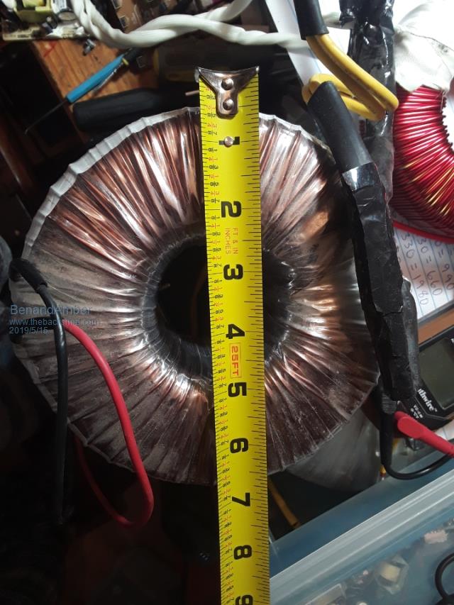 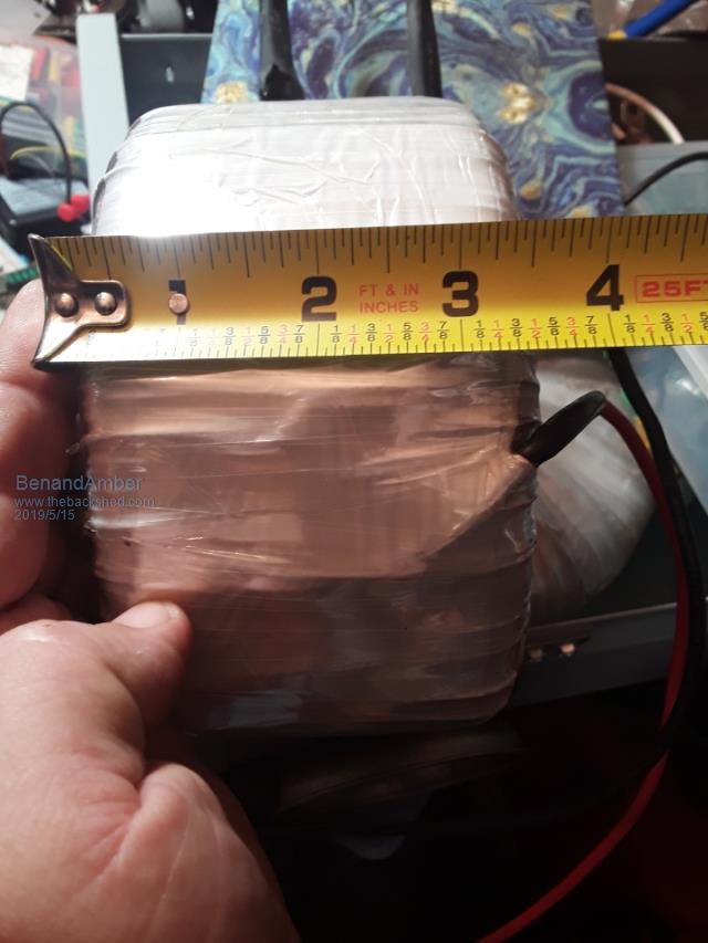 would this Transformer be good 4 a warpspeed inverter It came out of Amber's 8000 Watt 230 volt Power jack inverter And if so which one of the three Transformers that a warp speed inverter uses would it be good for and how many watts be warned i am good parrot but Dumber than a box of rocks |
||||
| Warpspeed Guru Joined: 09/08/2007 Location: AustraliaPosts: 4406 |
Very difficult to judge. You would need to strip off all the wire and measure up the bare core. From that you can then calculate the required number of turns on both the primary and the secondary. Then its a case of working out what wire sizes will actually fit onto that core while still being able to reach the required number of turns. Trying to guess all of that from just a picture is not really possible. Cheers, Tony. |
||||
| LadyN Guru Joined: 26/01/2019 Location: United StatesPosts: 408 |
From what I have been reading about Power jack, they mention the inverter rating as peak surge. So their 8000 Watt can handle 8kW surge. If the surge rating is 10x the continuous rating, we can assume it's a 1kW capable core. Since there is a lot of handwaving here, we can rephrase 1kW to mean 1kVA, so with the 300VA cores from a previous batch, this can be turned into a very nice 4 stage 1kW nominal Warpverter that can handle 8kW surge. What do you think Tony? I know the numbers are far from accurate, but would it be too far off to say that using this core as the primary inverter and 3 smaller stages, a 1kW nominal Warpverter that can handle 8kW surge could be made? In that case, I can work with Ben to have them make a Warpverter. They can use the Andrew STM32 board as the brain to start off with since it's signal compatible with your stock board? |
||||
| Warpspeed Guru Joined: 09/08/2007 Location: AustraliaPosts: 4406 |
The core itself does not really have a direct power rating. Power rating only refers to the allowable maximum "safe" temperature rise, and its the wire that gets hot, not the core. How you decide to use that core will determine the final continuous power capability, and thermal mass will pretty much set the surge limit, assuming your mosfets or something else does not blow up first. Its fun to speculate, but it really comes down to measuring it all up and deciding what is practical as far as the number of turns required, and the wire sizes that will actually fit through the available hole size. There is no simple one step formula to tie all these variables together. Its an iterative process where you try a whole lot of different combinations, juggle the figures around, to try and reach something you feel is practical to finally build. I can only suggest that you base your design on 1.0 Tesla (10,000 Gauss) flux density in the core, and 4 amps per mm squared current density in the wire, or figures reasonably close to those. Those figures will tell you the number of turns and the required wire sizes. If it will fit onto the core, fine. If not you will need to change something until it will fit. Its no good showing me a picture of some transformer and asking me will this handle xxx watts ? I have absolutely no idea. Cheers, Tony. |
||||
| Tinker Guru Joined: 07/11/2007 Location: AustraliaPosts: 1904 |
Ben, I have here a 1KVA rated toroid which looks of a similar size than the one you pictured. I will be using it for #4 (the smallest) toroid, simply because the hole is too small to feed a lot of turns through, as required with the other, bigger voltage, toroids. For your #1 (biggest) toroid look for something that has a 3.5" hole left when all the wires are removed if you want something capable of a few KW. I would suggest you put the building a warpinverter plan on the shelf for a while and cut your teeth with building a decent size single toroid inverter from *scratch*, that means no pre assembled Chinese kit boards. By the time you got that running with no blow ups you learned enough about toroids and how to rate them to proceed to a warp inverter - which is a much more complex beast with its 4 toroids to calculate windings for. Klaus |
||||
| BenandAmber Guru Joined: 16/02/2019 Location: United StatesPosts: 961 |
D3 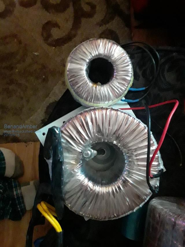 Power Jack buy a known 300 VA Transformer 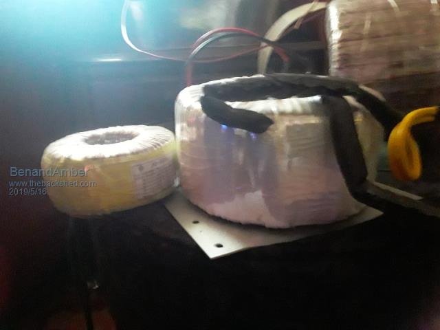 I think we have some very wise people on this form These wise people repeat the same things over and over If I was a wise one I don't know if I can have this same Grace and humility It tuck me 5 or 10 times but the wise one was patient and I finally got it With that being said I truly think this Transformer would have no problem doing three to four thousand Watts continuously I am new to all this so don't take my word for it there's much smarter people on this form And by the way there are videos on YouTube showing this exact same inverter doing 3 to 4000 Watts continuously with no problem YouTube can be faked so make your own opinions If I was to use this Transformer I would at the very least double up the secondary the high side And use a totally different low side primary And the hole is big enough to fit these modifications Keep in mind all my experience so far with this is 120 volts which requires a lot less turns than 220 volts I still haven't figured out how to square a round wire to go off warp speed 2 millimeter squared for 4 Amps So I've been using American Standard guide to tell how many amps a wire can handle And I don't go off chassis wire guide and I wouldn't recommend anybody to After I figure out how many amps a wire can handle i d rated a little bit like for a 12 gauge wire I say 18 amps instead of 20 and so on I really would like to understand warpspeed rating I know what he says is Gospel I've looked it up and I just can't wrap my head around it yet If anyone has a simple way to square a round wire that a dummy like me can understand please post it I really appreciate everybody's time be warned i am good parrot but Dumber than a box of rocks |
||||
| tinyt Guru Joined: 12/11/2017 Location: United StatesPosts: 438 |
It is difficult for me to do calculations now. But I find tables easier. So now I go to the internet and use something similar to this table. So looking at the conductor cross section in mm(sq) column, I find 2.08 has the closest equivalent to AWG #14. |
||||
renewableMark Guru Joined: 09/12/2017 Location: AustraliaPosts: 1678 |
Looks like a decent size Ben. Here are some pics of a fully wound 3kw aerosharp 240v for size reference. Like Tony said it will depend on stripping it, doing calculations and rewinding it to know exactly what you have. Looks like a reasonable size and there is still a 2.5 inch hole in the centre on yours. 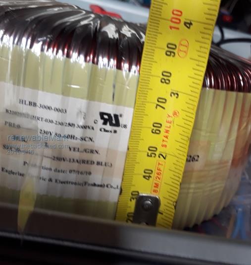 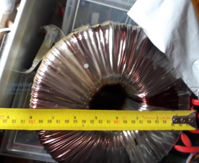 Cheers Caveman Mark Off grid eastern Melb |
||||
| Warpspeed Guru Joined: 09/08/2007 Location: AustraliaPosts: 4406 |
How much current should a wire carry ? There are at least two different answers to that question. The first is if you want to run a very long wire(s), where voltage drop becomes a serious consideration, maybe for some low voltage solar panels for example. Its not much help if the wire is so long and so thin that you end up losing half the voltage at the far end. The second consideration is how hot can we allow the wire to get ? Suppose the wire is only two feet long, voltage drop is never going to be an issue. But it might get dangerously hot if the wire is too thin. So we look at Tiny's chart for AWG14 and we find that the recommended maximum current for power transmission is 5.9 amps. That is the figure recommended for running long wires (usually at full mains voltage) as a first quick guess for suitability. There has to be a reasonable maximum length, and its usually applicable to one floor of a typical building, maybe 100 feet or less. For short lengths of wire inside equipment, say three feet long or less, we use the chassis wiring figure, which for AWG14 is 32 amps. Transformer windings are different, because we are coiling the wire up into a very confined space, and it will get a lot hotter than exposed chassis wiring. So a reasonable guess might be four amps per mm squared. Now we look at our chart and find that AWG14 has a diameter of 1.628mm. If we use the pi R squared formula to find the area, we get something like 3.142 x 0.814 x 0.814 = 2.08 mm squared. That is a wire cross sectional area of 2.08mm x 2.08mm. For use in a typical transformer we assume 4 amps per mm squared as a reasonably safe average design current. So we can say that safe maximum working current for AWG14 might be: 5.9 amps for wiring runs within a building (but not for very long runs between buildings). 8.3 amps for winding a transformer. 32 amps for very short fully exposed chassis wiring (not multiple bundled cables). Cheers, Tony. |
||||
| BenandAmber Guru Joined: 16/02/2019 Location: United StatesPosts: 961 |
I think I need to look up pie squared and keep studying at till I figure it out I have used 2 Square wires that each are a little over 3mm by 3 mm So I am assuming that not including the coating they are exactly 3mm by 3 mm I am wrapping them I think you call it two in hand 2 wires making one wire for the 110/120 output of the Transformer I just built I was hoping this Transformer would do 4 to 5000 Watts I thought I was overdoing it by a long shot but maybe I'm not maybe it's not even good enough As for the power jack Transformer the output wires on it are 14 gauge single winding 230-volt no Center tap I have read that these Transformers get really hot at anything over around 3000 to 4000 watt depending on what model of 8000 watt power jack unit it came out of Warp speed your word is like the gospel and it needs to be spread here because this is a safety issue And I don't want to lead someone the wrong way that would be awful Just my two cents be warned i am good parrot but Dumber than a box of rocks |
||||
| Warpspeed Guru Joined: 09/08/2007 Location: AustraliaPosts: 4406 |
Once you have stripped all of the wire off a candidate toroidal core, you then at least have a fighting chance of making a GUESS about the power capability. First thing is to measure the core cross sectional area (height x width). If we decide to use 1 Tesla as our design flux density, we can use one of the many on line flux calculators to give us a figure for volts per turn. It might be somewhere between 0.2 volts per turn for something small, and 1.0 volts per turn for a monster toroid. Or even something outside that range. Let's assume 0.5 volts per turn in this example. Second step is to measure the hole diameter, and convert that to area using pi R squared. This might be a three inch hole, say 76.2mm diameter. That works out to 4,561 square mm hole area. The only thing we can say for sure, is that a well designed transformer has equal copper areas in the primary and secondary. The turns and wire sizes will be different, but the total copper area (turns x wire areas) should be close to being the same. So if our hole has 4,561 square mm total area, we can allow half of that or say 2,280 square area for each winding. Now here it starts to get a bit hairy, because we cannot totally fill all of that available area with copper. The wires are round and there will be a lot of wasted space between turns, and also layers of necessary insulation to account for. A single perfect winding can approach 60% copper fill. For home brew it will probably be closer to 50% copper fill, and if we allow for some layers of mylar tape it could fall as low as 40% copper fill. So we place our bets and to be safe assume 40% copper fill of our 2,280 square mm of available hole area. Now we are only trying to guess the power capability of this core, not design an actual transformer. So let's start with 40% of 2,280 sq mm = 912 sq mm of actual copper in one winding. And lets further assume we fill that space with 912 turns of 1.0mm squared copper wire. Now we have already worked out in the very first step that we can run the core at 0.5 volts per turn, so we will have a 456 volt winding with 912 turns. And if we make our wire current density 4 amps per mm squared, we can safely load our 912 turn winding to 4 amps. S 456 volts x 4 amps = 1,824 watts (or more precisely 1.824Kva). Now we might not want a 456 volt winding. But we can fit fewer turns of larger wire to get the voltage we want, but it still can have no more than 2,280 copper area. One third the turns of 3mm squared wire will still work out as 1.8Kva, as all we wanted to do here is get a rough power estimate. If it all looks good, we then start to work out our final correct turns and wire sizes. Now maybe 40% copper fill is pessimistic and it will all fit easily with room to spare. Maybe we could have risked 50% fill and got away with it, or maybe not. It all involves a lot of guessing even if you have the exact toriod dimensions. Being shown a picture of a fully wound transformer and having no idea of the core dimensions its just not possible to come even close to guessing. Cheers, Tony. |
||||
| Warpspeed Guru Joined: 09/08/2007 Location: AustraliaPosts: 4406 |
I stuffed that up. 2.08mm squared is a wire cross sectional area of 2.08mm x 1mm. Cheers, Tony. |
||||
| Warpspeed Guru Joined: 09/08/2007 Location: AustraliaPosts: 4406 |
Trying to estimate how many turns will fit onto any particular transformer core is very difficult. Its like trying to guess how many tennis balls will fit into a bucket. When there also has to be extra space allowed for layers of insulation, and possibly an electrostatic screen, it becomes more a matter of luck and good judgement rather than being able to calculate it all out precisely beforehand. As Klaus says, start by winding a few of your own transformers. After a few attempts you will quickly gain experience, and your guessing will become much better. Cheers, Tony. |
||||
| BenandAmber Guru Joined: 16/02/2019 Location: United StatesPosts: 961 |
Boy that is complicated I think I'm going to bail out And not even speak of such a thing anymore I don't want to lead anybody wrong and cause any safety issues I can say I have not got a clue so don't go off anything I say without checking it for yourself several times 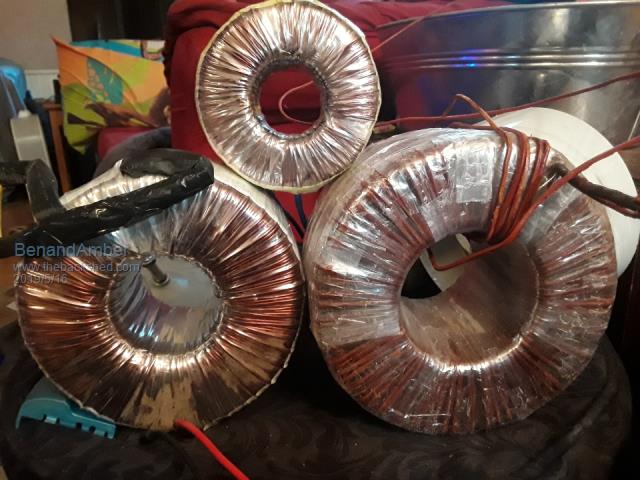 Warpspeed sorry for unanswerable questions The Transformer on the left is the Transformer out of the 8000 watt power Jack the Transformer on the right is the one I'm in the process of winding it will be replacing the one that's on the left and be put back into the Power Jack it only has 44 turns on it so far and it will have 100 to 110 turns when done it's the one I made from a bunch of little ones the one on the top is almost identical to the ones I tore apart to make the big one The really nice Big tin in the background was a gift from a really awesome person It came full of goodies we now use it for a giant candy and snack dish for all the neighborhood kids be warned i am good parrot but Dumber than a box of rocks |
||||
| Warpspeed Guru Joined: 09/08/2007 Location: AustraliaPosts: 4406 |
Yes its complicated. And its why when you ask what can a particular transformer do, nobody is going to be able to be able to give an exact answer from just a picture. If you are serious, strip it down to the bare core, measure it all up, and THEN ask the question. Cheers, Tony. |
||||
| BenandAmber Guru Joined: 16/02/2019 Location: United StatesPosts: 961 |
Yes sir will do Check this out warpspeed I got two of these for $41 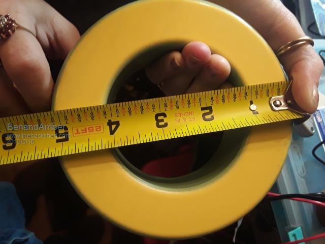 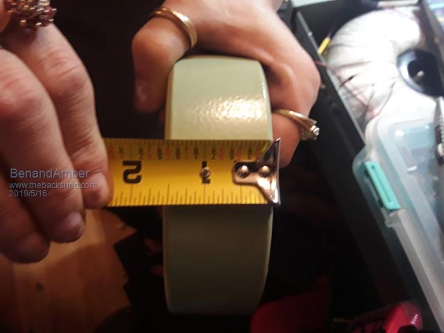 They came wrapped with some really nice wire Biggest ferret chokes I've ever seen I have a post on these called big chokes I updated it just a few minutes ago It has all the information where I bought them that if anybody's interested in some for their self be warned i am good parrot but Dumber than a box of rocks |
||||
| LadyN Guru Joined: 26/01/2019 Location: United StatesPosts: 408 |
Ben, hang in there! Please. Don't give up on this as I am not giving up either. We will all have a working DIY inverter. I know it! I understand your frustration - you are likely torn between the two diametrically opposite information about the same toroid - the PJ Inverter says its good for 8kW while the highly experienced gurus here are now suggesting even 1kW might be too much to ask of this. If you remember earlier - just from a purely theoretical and naive steps I estimated this core would be good for 1kW. The gurus here who have actually done this before want us to ease our expectations further and with much good cause. Pay heed to their words as it comes from a place of wisdom and experience. I pay full attention to it as I lack that completely. If I do have the ability to make a recommendation to you: it's this - make an inverter from scratch. Be it the ozVerter or the WarpVerter - make it from scratch. No outside kits. Maybe a few PCBs because the power MOSFET layout at the levels we are operating at is way involved than I originally imagined. For example, we can parallel 24 MOSFETs as much as we want, and perhaps it will even work. But the physics is undeniable - technical debt will eventually catch up with the debtor, perhaps at a time when you most depend on it! I spent an entire week studying just the parallel MOSFETs considerations - ensuring the trace characteristics to each MOSFET in the array and how to get it right. I came to the conclusion that there was no way around it - I would have to go back to the basics instead of hoping things would just work. Because it well might work. For a few hours. For a few days. For a few months even. That kind of (un)reliability can be purchased online for a couple of hundred dollars without all the frustration, late nights and pages and pages of reading: but we are building our own because we can do better. |
||||
| BenandAmber Guru Joined: 16/02/2019 Location: United StatesPosts: 961 |
LadyN Amber's and I are just trying to get you where you need to be to build you a workin inverter When I build my warpspeed inverter I'm doing it with square Transformers Just like the master himself and I won't be deviating not even in the slightest I'm already old and don't have a lifetime to gain the experience I would need to go off on my own And I know if warp speed or a few others on here says something it's true if Power Jack will run at 3000 Watts and they say it's good for 1800 watts then there's something dangerous going on We all have families and don't want to do anything dangerous That's why I decided to shut my mouth about the situation altogether don't want to lead somebody wrong too big of consequences I'm understanding more and more day by day why warpspeed poida the great renewable mark tinker tinyt and many others I've left out are so careful about what they say Sorry for the ones I left many others very careful also be warned i am good parrot but Dumber than a box of rocks |
||||
| BenandAmber Guru Joined: 16/02/2019 Location: United StatesPosts: 961 |
Did nobody see those ginormous ferrite choke 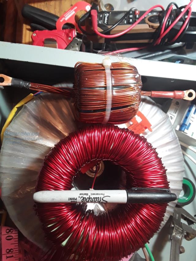 I got worried that the wire wasn't big enough on the original one I made for my 10000 watt inverter board The little one in this pic is the first one I made it has 10 2 mm wires as one The big one has 16 in hand or whatever you call it made in one I hope that wires big enough I don't know how to do pie squared so 2mm is just the single measurement And it's round wire The Transformers wires are still way bigger yeah it has two 2awg wires in hand So four all together for the low side of the Transformer I am hoping to get 4 to 5000 watt continuous Even though I probably won't be using over 1500 watts most the time be warned i am good parrot but Dumber than a box of rocks |
||||