|

|
Forum Index : Electronics : 24v Portable Mini Inverter
| Author | Message | ||||
| Solar Mike Guru Joined: 08/02/2015 Location: New ZealandPosts: 1138 |
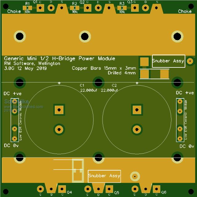
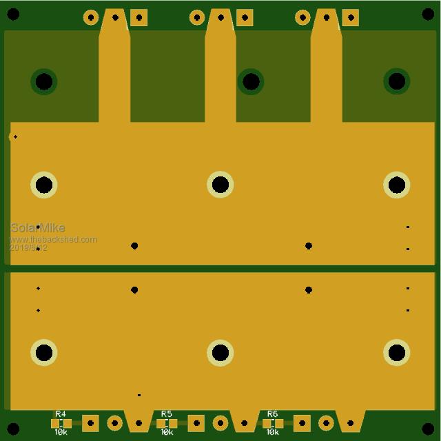
While waiting for pcbs to arrive from China for other projects, though I would start the design of a small portable LF inverter, powered from 8 x 200AH Lifepo4 cells. AS only one inverter is required thought I would use this as a test project to explore further ideas on inverter design. Basic Spec: Input voltage 24vdc, power output 0 - 1.5 KW continuous, 5 KW peak for 5 minutes, modular construction so sub modules can be re-used. H-Bridge all 4 sides opto-coupled, cpu Poida's Nano concept. Have decided to use multiple small pcbs for the power stages, under 100mm to keep costs down, this leaves almost nill room to place any driver components on the power boards, so the driver boards will sit vertically atop the mosfet pins soldering directly to the power board pads. I like this idea as everything is re-usable and can be utilized in other designs. High current pcb's are virtually place holders for the mosfets and additional power bars soldered to the pcb, it gets very expensive to get 4oz boards made in the small DIY quantities. So will use 1oz with 10 x 2mm copper bars soldered to surfaces where required. Have decided each 1/2 of the H-Bridge will be on its own pcb, thus two required to make a full circuit. Running off 24v here means big currents - 200 amps, so the design will use two full H-Bridge power stages in parallel using a single toroidal core, ( single CPU controller ), each set of pcbs will share the current so we have approx 100 amps per set. With lower voltages more capacitance is required, each 1/2 bridge will use 2 x 22,000 35v electro's as these are readily available in 35mm width; the Calb 200 AH batteries can certainly run at 200a until flat with no issues. 1/2 Bridge Power Board LHS: RHS Power Boards: Each quadrant uses 3 mosfets in parallel, combined have 1mR or less so the heating will be minimal, they are mounted under the pcb and bolted to an insulated finned heat sink, access via the 10mm holes in the pcb. Driver boards next, then I may build a schematic, nothing written down at the moment... Cheers Mike |
||||
| Ralph2k6 Senior Member Joined: 24/09/2017 Location: AustraliaPosts: 129 |
Very nice, can be useful as a backup for if a 'regular' home inverter cracks the sh*ts. 1.5kw continuous is still a decent amount of power for many applications. Will lurk with interest.  And I see 'only' around 60 something amps for rated 1.5kw output. Ralph |
||||
| Solar Mike Guru Joined: 08/02/2015 Location: New ZealandPosts: 1138 |
Start the portable drop saw and 200 amps for a short period is to be expected, so it has to survive that at least.. Mike |
||||
| Solar Mike Guru Joined: 08/02/2015 Location: New ZealandPosts: 1138 |
Here is the driver pcb, this one for the upper mosfets, need to clone and switch the Source\Gate connections over so it will fit the lower mosfets correctly. Note layout required to heat sink the driver chips. Mosfet source currents must not pass via this pcb, see breaks in -ve rail. Mike |
||||
| poida Guru Joined: 02/02/2017 Location: AustraliaPosts: 1419 |
I like this a lot. I can't quite picture the driver setup, but soon you probably will show more parts of the puzzle. For instance I don't get how the gate and source are connected. Onto the pins of the MOSFETs? Dunno. No hurry. The modular nature is important now since it lets things blow up if need be but not causing complete rebuilds of large boards. And cheaper PCB costs. wronger than a phone book full of wrong phone numbers |
||||
| LadyN Guru Joined: 26/01/2019 Location: United StatesPosts: 408 |
Mike, you can see why I am really excited about this. Will you be boosting the voltage from 24V to, say 100V and then use a 100V-220V stepup transformer-hbridge for the AC generation? 1. You mention LF, but what's the operating freq? 2. 1.5kw continuous meets my needs perfectly and will allow me to start up the window AC unit I have! 3. The 200A requirement is monster. I can probably pull off 40A continuous when I do get dad in invest in LTO batteries but that's a few years from now but I will learn and watch this project with a lot of excitement and interest so I can learn the fundamentals and attemp to rework it to my needs Thank you very much for sharing this. I can't wait to learn from it! |
||||
| BenandAmber Guru Joined: 16/02/2019 Location: United StatesPosts: 961 |
You might be very surprised at what 1500 watt of low-frequency will do I know I was be warned i am good parrot but Dumber than a box of rocks |
||||
| Solar Mike Guru Joined: 08/02/2015 Location: New ZealandPosts: 1138 |
Standard 24vdc to 230ac 50hz PWM = 20Khz inverter if using Nano driver board. No step up sorry. If using my analog driver PWM is 50 - 100 Khz bi-polar modulation. Mike |
||||
| Solar Mike Guru Joined: 08/02/2015 Location: New ZealandPosts: 1138 |
Bottom side driver: Driver board connections made direct to mosfet pins sticking out of power board, by a blob of solder. Next create a schematic, Diptrace doesn't reverse engineer, so once I have a pcb layout, unfortunately I cannot tell it to create the schema, despite it knowing all the components and nets...Nah such a simple design, schema not a high priority. Mike |
||||
| Solar Mike Guru Joined: 08/02/2015 Location: New ZealandPosts: 1138 |
I have decided to extend the driver pcbs to allow 5 mosfets, reason being is I started building a high power water cooled inverter some time ago and was waiting for an opportunity to develop better driver boards, as the mosfet spacing on the WC version is the same 24mm as this mini inverter, this is a good time to implement it. Not sure how copper pipes, water and 50v would work out, guess I will find out sometime... The resulting longer pcb has a cutting line marked, to chop off the excess with heavy duty tin-snips for use on the smaller board. In fact could also be cut after the next driver chip if a 4 mosfet version was required. Doesn't increase the costs to much |
||||
| Solar Mike Guru Joined: 08/02/2015 Location: New ZealandPosts: 1138 |
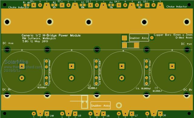
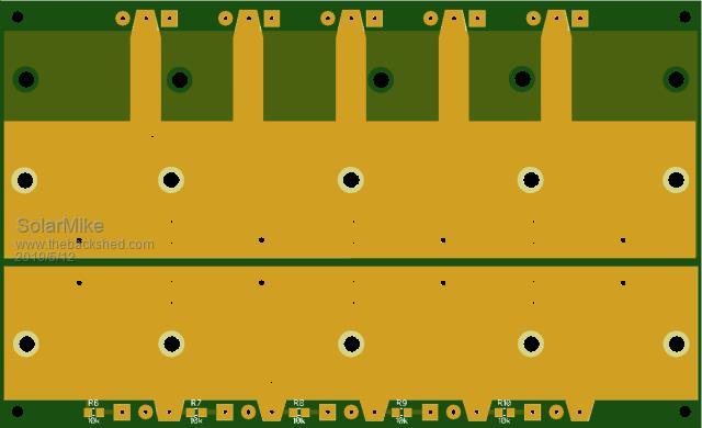
Decided the mini inverter needs a higher voltage "Bigger Brother" that has 5 mosfets in the 1/2 bridge to match up with the new driver; so a full bridge requires two boards + 4 of the driver pcb's outlined earlier. Quickly threw this board design together, +ve -ve main power rails run under the pcb and have 15mm x 3mm copper bars that bolt to the underside to carry a goodly amount of current, the top choke transformer connection has a single bar bolted to the top. The bars ( AliExpress ) can extent from either side for ease of positioning the boards, with a full complement of mosfets the pcb effectively mounts on their leads. Have fired off the gerbers to China, I've a lot to play with... Cheers Mike |
||||
| Solar Mike Guru Joined: 08/02/2015 Location: New ZealandPosts: 1138 |
After designing the Bigger 5 mosfet pcb decided it is a much better layout than the earlier 3 mosfet mini board; the earlier board required different pcbs for the LHS and RHS half bridges, so have dumped that board and cancelled the order. Have made a new 3 mosfet mini design (3G), same pcb can be used for both, keeps costs down when purchasing min lots of 5 boards. 3G Mini:   Bigger 5G Version:   Low ESR Ceramic Cap PCB, used on both boards: Has to be cut in half to make 2 tiny pcbs for 20 caps, of different sizes, these caps can destroy them selves by going short circuit if their voltage rating is exceeded, easier to replace if on their own pcb; and more modular.  The Driver boards can be used for both designs. Here are the gerber files if anyone wants to make one. 2019-05-12_164457_Gerbers_Generic_HBr_3G_0.zip 2019-05-12_164611_Gerbers_Generic_HBr_5G_0.zip 2019-05-12_164655_Gerbers_LowESRCap_Small.zip 2019-05-12_164728_Gerber_OptoDriver_4_1_3_5.zip 2019-05-12_164810_Gerber_OptoDriver_4_1R_3_5.zip Now I need a cpu board to test it... Cheers Mike |
||||
| poida Guru Joined: 02/02/2017 Location: AustraliaPosts: 1419 |
These look great. I wonder if I will ever find the time to make one of these. My pick would be the 3 FET board, to run the house. The 1 FET board just handy to have, for testing. wronger than a phone book full of wrong phone numbers |
||||
| Solar Mike Guru Joined: 08/02/2015 Location: New ZealandPosts: 1138 |
I have just sent all those zipped gerber files to JLCPCB, should get the boards back in approx 7 days, have opted for 2oz on the power boards only, ouch! costs increase dramatically. Cheers Mike |
||||
| johnmc Senior Member Joined: 21/01/2011 Location: AustraliaPosts: 282 |
Thanks for the pics and watching the development with interest. cheers john johnmc |
||||
| Tinker Guru Joined: 07/11/2007 Location: AustraliaPosts: 1904 |
Mike, what is the purpose of that many "low ESR" capacitors in parallel? Aren't those big caps enough? Klaus |
||||
| yahoo2 Guru Joined: 05/04/2011 Location: AustraliaPosts: 1166 |
I wouldn't worry to much, even manky ol LFP cells can output some incredible amps for 30 seconds before they start to get warm. I have seen them max out the amps at roughly 9 times the Ah rating while we were testing fuses and cables. I have a welder that will stop a 7 kw genset (it wants 12 kw) however a 400ah 24volt calb battery bank and a proper 3 kw inverter toys with it for 15-40 minutes of solid welding. I'm confused, no wait... maybe I'm not... |
||||
| Solar Mike Guru Joined: 08/02/2015 Location: New ZealandPosts: 1138 |
Their purpose is low esr at high frequencies, similar to your use in the LF Inverter Driver Mother board schematic with its 4 x 0.22uf poly caps placed across the supply rails. The big caps provide bulk energy storage, the little ones supply the HF energy storage. Normally I mount these small smd ceramics directly under the main big caps on the mother board, for the 50 vdc inverter 250 - 500 vdc ratings are required, they easily go short circuit if their voltage is exceeded and generally burn holes in the pcb. If purchasing these from China there is no guarantee they meet voltage ratings spec, so have to be treated with caution. Placing a number in parallel on a small pcb allows easy replacement should one or more go short; another solution is use multiples of two in series to increase their combined voltage, if one shorted the other may not. Mike |
||||
| BenandAmber Guru Joined: 16/02/2019 Location: United StatesPosts: 961 |
I have been wondering for a while now what the little capacitors were for Now I know thanks be warned i am good parrot but Dumber than a box of rocks |
||||