|

|
Forum Index : Electronics : What can I expect from this transformer ?
| Author | Message | ||||
| BenandAmber Guru Joined: 16/02/2019 Location: United StatesPosts: 961 |
Thanks for explaining that poida And thanks warp speed for explaining your setup From the way I understand it mosfets will only do a small fraction of their specs sheet ratings be warned i am good parrot but Dumber than a box of rocks |
||||
| nickskethisniks Guru Joined: 17/10/2017 Location: BelgiumPosts: 458 |
Yes, current sharing, lower combined rdson, lower power loss due lower rdson,... And keep in mind allthough it maybe handles 200A in ideal conditions. I would not use this mosfet higher than 20A continuous (40A T=1/2) in this application. |
||||
| Warpspeed Guru Joined: 09/08/2007 Location: AustraliaPosts: 4406 |
From the way I understand it mosfets will only do a small fraction of their specs sheet ratings Not true, unless its a counterfeit fake chip. But you need to UNDERSTAND what you are reading in the specification sheet. You see something like 200 watts, 100 amps at a junction temperature of 25 Celsius. And that is all true. But to keep the junction temperature at 25C we need to read further and find that the thermal resistance junction to case is 0.1 degree Celsius per watt. If we are pushing 100 watts then the heatsink has to be ten degrees cooler than the junction. How can we possibly keep the heatsink at only 15 degrees Celsius on a hot day ??? Just not possible. So we work out that on a 40C day the heatsink might need to run at 65C or something, and the junction will be even hotter than that. So we need to DERATE both our maximum rated power and maximum rated current, so its working within the specifications on the data sheet. It can still do 200 watts and 100 amps, but only if you use water cooling or a refrigeration plant to keep it cool. So why advertise it as 200 watts and 100 amps if that can never be achieved in practice. Its not meant to be what the device can actually do, but sets the limits so you can then apply suitable de-rating factor to suit your own actual requirements. You will also find a maximum junction temperature of 160 Celsius in the specifications. So its full advertised power and current at 25C junction temperature. And ZERO advertised power and current at 160 Celsius. Figure out what temperature you plan to run it at, and stay well below that. Remember these are the MAXIMUM ratings above which the device will fail. You don't run it right up to the failure point. So it always ends up that the actual final safe operating conditions are usually only a small fraction of the advertised figures, if you go through the whole design process and do it properly and add some suitable safe margin. Cheers, Tony. |
||||
| LadyN Guru Joined: 26/01/2019 Location: United StatesPosts: 408 |
Yes, current sharing, lower combined rdson, lower power loss due lower rdson,... And keep in mind allthough it maybe handles 200A in ideal conditions. I would not use this mosfet higher than 20A continuous (40A T=1/2) in this application. By T=1/2 did you mean 50% duty cycle? Figure out what temperature you plan to run it at, and stay well below that. Remember these are the MAXIMUM ratings above which the device will fail. You don't run it right up to the failure point. So it always ends up that the actual final safe operating conditions are usually only a small fraction of the advertised figures, if you go through the whole design process and do it properly and add some suitable safe margin. This is important to understand well. I created a new thread to learn about this here https://www.thebackshed.com/forum/forum_posts.asp?TID=11355&PN=1&TPN=1 |
||||
| hary Regular Member Joined: 15/04/2019 Location: FrancePosts: 89 |
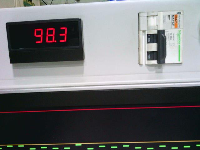
Then quite separately order a shunt trip, with a suitably rated coil voltage.  Warpspeed. That's exactly what I'm looking for the same application you use it. Would it be possible to have a link ? They seem to be very hard to find. |
||||