|

|
Forum Index : Electronics : Cheap 48 volt battery charger
| Author | Message | ||||
| BenandAmber Guru Joined: 16/02/2019 Location: United StatesPosts: 961 |
I've ordered a battery control module off of eBay when it comes in I'm going to wind Giant Transformer core I have and hopefully make a pretty decent battery charger in case there's one day that my solar panels don't fully charge my battery Bank I might be going about this all the wrong way the module I ordered is adjustable and it goes on the Mains voltage side of the Transformer 30 amp relay on the board that turns the Transformer off at the set voltage of the low side I'm thinking this may be able to give me 60 or so amps on the low side of the Transformer but I could be very wrong any comments would greatly be appreciated be warned i am good parrot but Dumber than a box of rocks |
||||
| LadyN Guru Joined: 26/01/2019 Location: United StatesPosts: 408 |
Do you have a link to the product? The oldest types are shunt type chargers. The "more efficient" ones are PWM type. The better ones are what DavePoz and opera are making that uses MPPC. Check out their channel here: https://www.youtube.com/watch?v=GUQeQpv6Woc opera is a very very smart engineer. |
||||
| BenandAmber Guru Joined: 16/02/2019 Location: United StatesPosts: 961 |
The module I ordered is off of eBay I'm not sure what technology uses I know you can set the voltage to shut off at 0 to 60 volts I'm not sure that it will work the way I want it to but I have a giant Transformer core it weighs about 60 pounds without copper on it so I am hoping to only be limited by the outlet I plug it into which in itself might be a problem it might flip a 20 amp 110 breaker so I might have to figure out a way not to draw too much current so it don't flip a breaker I'm sure someone on here will probably comment this place is awesome it has so many extremely intelligent people that don't care or charge you for some really good advice some of those people that believe in the philosophy of what goes around comes around and put Good Vibes out everywhere to try to make the world a better place really happy to be a part of it be warned i am good parrot but Dumber than a box of rocks |
||||
| noneyabussiness Guru Joined: 31/07/2017 Location: AustraliaPosts: 513 |
inverter welder Some of us use these, out of the box they work well (around 2-3kw depending on model) however throw a few extra turns on the " transformer " inside and i can safely pump 4kw from grid/genny all day if need be... I think it works !! |
||||
| LadyN Guru Joined: 26/01/2019 Location: United StatesPosts: 408 |
Glen, so you purchase these for the toroids? What specs do they come out of the box |
||||
| BenandAmber Guru Joined: 16/02/2019 Location: United StatesPosts: 961 |
No they use them right out of the box like he said I read a post about it somewhere here while back very very interesting they're very light and easy to carry around I guess some people on here do maintenance on other people's battery Banks and solar stuff and those little welders are really light and put out a lot of amperage if I remember correctly yeah that's awesome if I didn't already have this other stuff ordered I would definitely go that route I might still go that route I just don't know what to do with this giant Transformer core I have maybe somebody on here has a good idea what to do with it or maybe somebody else will be willing to pay the shipping for them to do something with it be warned i am good parrot but Dumber than a box of rocks |
||||
| BenandAmber Guru Joined: 16/02/2019 Location: United StatesPosts: 961 |
Hay ladyN I have a couple of those Direct washing machine motors also you know they're kind of like the Fisher and Paykel I guess they work the same from what I've read people make windmills out of them lots of other things to I have an extra one if anybody wants one but whoever wants it will have to figure the shipping out I don't care to box it send it out I just don't know what company do you use to get it done the cheapest be warned i am good parrot but Dumber than a box of rocks |
||||
| BenandAmber Guru Joined: 16/02/2019 Location: United StatesPosts: 961 |
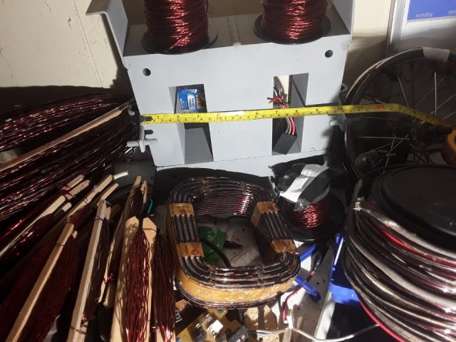
 This is the big heavy Transformer core I was planning on making into a 48v battery bank charger be warned i am good parrot but Dumber than a box of rocks |
||||
| BenandAmber Guru Joined: 16/02/2019 Location: United StatesPosts: 961 |
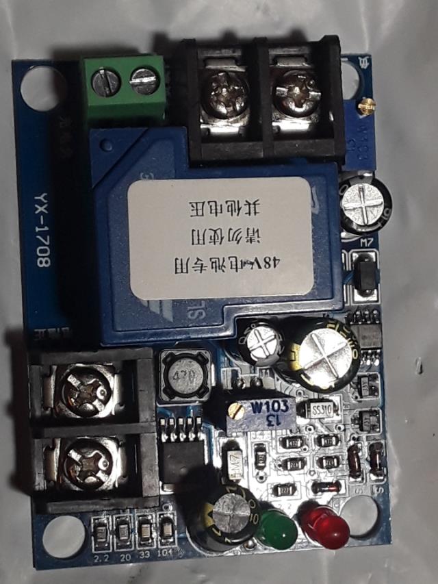
 This is the little shut off module I ordered off eBay It was under $10 including shipping got to love that China stuff If I understand it right it has a 30 amp relay on there that goes on the main side of the Transformer in series So on the secondary I was thinking I should at least be able to get 60 amps including all the losses is this thing so big it will flip the 20 amp 1 20 volt breaker with a really dead battery Bank I think that breaker will probably flip it around 18 amps the breaker should do a little over 2,000 Watts at 60 amps should only be about a thousand Watts on the secondary other Transformer I may be going at this all the wrong way I may need something to limit the amps please chime in I appreciate the help be warned i am good parrot but Dumber than a box of rocks |
||||
| BenandAmber Guru Joined: 16/02/2019 Location: United StatesPosts: 961 |
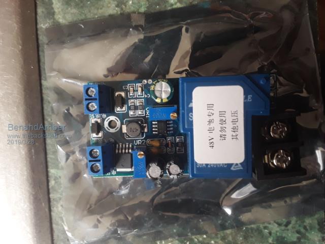
 Picture above was the wrong module shipper sent the wrong one so I ordered the right one be warned i am good parrot but Dumber than a box of rocks |
||||
| BenandAmber Guru Joined: 16/02/2019 Location: United StatesPosts: 961 |
Okay back to the battery charger This battery charger will be permanently mounted to the rv The weight does not matter the heavier the better I would like for it to be as maintenance-free and tough as possible Most likely I will never use it I just want it there in case I ever do need it It needs to be able to charge both 12 volt And 48 volt batteries It does not have to be automatic shut-off If I am traveling and my battery Bank is low I need to be able to plug into a 110/120 volt 20 amp Outlet without tripping it That would not be good at a restaurant friends house or gas station I need to be able to limit the input current and the output current And the way I see it if I limit one it automatically does the other I do not want to burn my batteries up by too many amps I would like to be able to select how many amps goes into the batteries whether it be on the 12 volt output or the 48 volt output On the 12 volt the amperage could be as high as 150 and the 48 volt side 50 The Transformer I will be using will be more than capable of these amperages I do not want to use light bulbs for current control But I don't mind winding inductors if I can do it that away If you've read this far you are either bored or really like to help people lol So how do you think I could do this or is it not possible be warned i am good parrot but Dumber than a box of rocks |
||||
| nickskethisniks Guru Joined: 17/10/2017 Location: BelgiumPosts: 458 |
I think the first thing you want to do is to define your needs. Like: Capable running on 110/120V charge current 12V charge current 24V What are you using then? Buck converter technology? Option 1 What you can try is to feed an mppt controller or buck converter with you transformer if you rectify your voltage first. You need to be able to adjust the maximum output current on the controller. Otherwise you burn the controller/converter. Option 2 The same as the first but DIY. Make a mppt controller, maybe the one SolarMike is making? I don't know if it has current limit. Option 3 Use your transformer, rectify it, (best to use capacitor and inductor for lower ripple) use your module to set the cut out voltage. Then put a series resistor between your output and battery to limit the current. You will dissipate a lot of heat with low battery level, but I think the most reliable solution if you don't count the chinese module. Option 4 Make your own buck converter that you feed with your rectified transformer. Similar to option 2. Maybe others have other ideas? |
||||
| BenandAmber Guru Joined: 16/02/2019 Location: United StatesPosts: 961 |
I was hoping to do two windings on one Transformer one for the 12 volt one for the 48 volt I was hoping there was some way to limit current the didn't require Electronics other than Bridge rectifier and maybe a capacitor Would a capacitor on the mains side series connection limit the amperage How about a inductor kind of like a ballast not See this thing probably will never get used I just want to bolt it down in the back of a bay and forget about it Not much can go wrong with the Transformer Bridge rectifier and a capacitor So I was just wanting something very simple if possible that's not likely to ever stop working be warned i am good parrot but Dumber than a box of rocks |
||||
| LadyN Guru Joined: 26/01/2019 Location: United StatesPosts: 408 |
sure, many ways. Are you trying to control the inrush current? Write your needs in details. Yes, it could but it needs to be rated It could work too but then you have to figure out a way to handle the voltage on flux collapse In that case, why dont you use a NTC? Depending on what your needs are, a TL431 based solution could work well. You can easily build it |
||||
| BenandAmber Guru Joined: 16/02/2019 Location: United StatesPosts: 961 |
I'm thinking now just to make it for the 48-volt battery bank just to simplify I just need this thing not to pull no more than around 2,000 Watts And I don't know how Dependable a lightbulb would be so I'm trying to do it a different way but a very simple way Would a big wire wound resistor work or would it put off too much heat and waste too much energy I also have a bunch of tanning bed ballast With those worked limit current on the input be warned i am good parrot but Dumber than a box of rocks |
||||
| BenandAmber Guru Joined: 16/02/2019 Location: United StatesPosts: 961 |
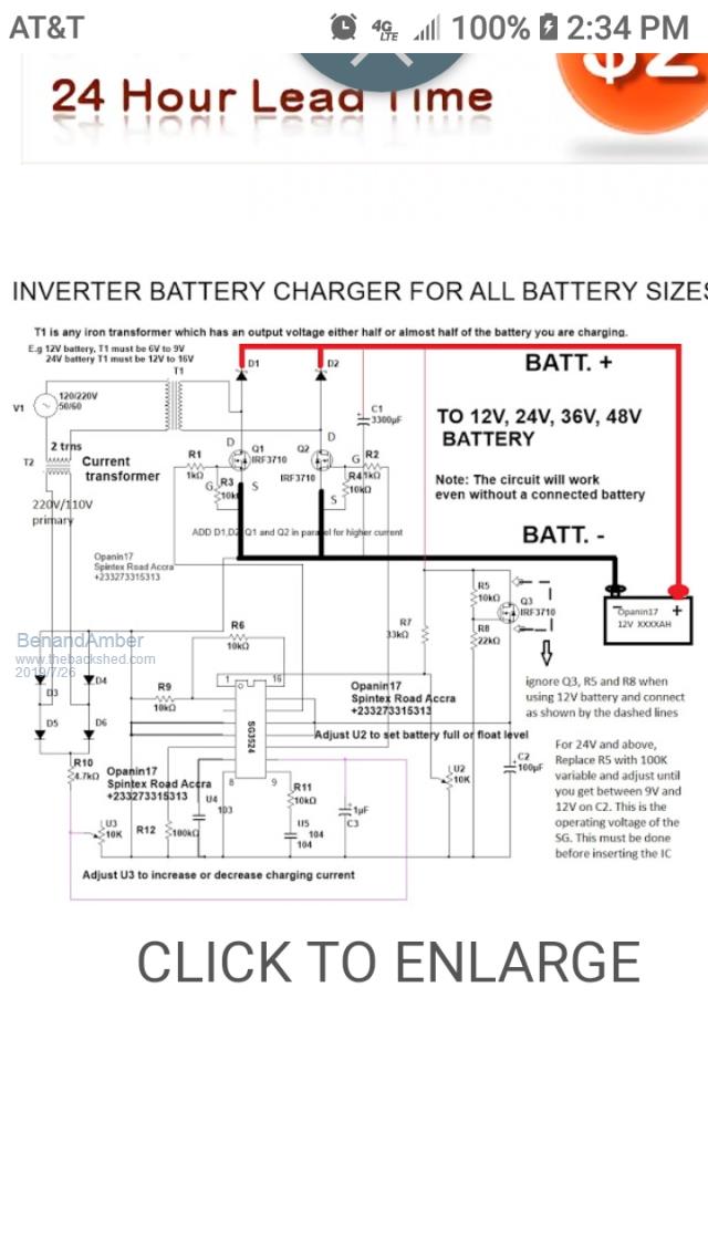
 Any thoughts on this battery charging circuit In this post earlier somebody mentioned using an mppt charge controller which sounds pretty awesome also be warned i am good parrot but Dumber than a box of rocks |
||||
| Warpspeed Guru Joined: 09/08/2007 Location: AustraliaPosts: 4406 |
The way I do it if I want to charge off the grid, when there is no sun, is I feed the output of a simple mains powered rectifier into where the solar panels feed my charge controller. Solar panel voltage here varies between about 105v and 145v, and my rectifier puts out around 116v. So the system runs from the rectifier to charge the battery, and if the sun comes back, that takes the load off the rectifier. The mains voltage does not need to be controlled or regulated, and the normal battery charger and BMS ensures the battery will not be fried if I forget to disconnect the rectifier. The whole system continues to run (from the rectifer) if the battery is disconnected for maintenance, and there is also no sun. Cheers, Tony. |
||||
mackoffgrid Guru Joined: 13/03/2017 Location: AustraliaPosts: 460 |
I presume the rectifier has a large choke? How much ripple do you get from the rectifier? Do you see the effect of the ripple in the output? Cheers Andrew |
||||
| Warpspeed Guru Joined: 09/08/2007 Location: AustraliaPosts: 4406 |
My rectifier is actually three phase, and yes there is a choke. Its a 2.5mH 30amp job resurrected from an Inspire grid tie inverter. Ripple from the six diode bridge (without any filtering) is around 2% to 3% rms. On the output side on the choke is 36,000uF located at the Warpverter. Ripple will be negligible. I ran this for just over a year without any battery at all. The rectifier provided night time power, and the solar panels took over during the day. A very smooth transition too, both ways with just diodes to steer the current. These days the rectifier remains switched off at the mains, unless I have a specific reason to fire it up. Cheers, Tony. |
||||
| Solar Mike Guru Joined: 08/02/2015 Location: New ZealandPosts: 1138 |
|
||||